Flexible optical fiber cable

A fiber optic cable, flexible technology, applied in the field of optical fiber communication, can solve the problems of small braiding distance, difficulty in adjustment, and bending resistance of optical fiber, etc., and achieve the effect of improving tensile strength, bending resistance and bending resistance

Pending Publication Date: 2021-06-22
龙岩岳凯科技有限公司
View PDF0 Cites 0 Cited by
  • Summary
  • Abstract
  • Description
  • Claims
  • Application Information

AI Technical Summary

Problems solved by technology

The flexible optical fiber in the prior art usually includes an optical fiber and a sheath outside the optical fiber. The bending radius (also called bending radius) of the flexible optical fiber is the bending radius of the optical fiber. It is generally recommended to be about 30 mm. However, in In practical applications, the bending radius of the flexible optical fiber cable by the user or construction personnel is often smaller than the recommended value, resulting in the phenomenon that the optical fiber is often broken
Therefore, the flexible optical fiber wires of the prior art have poor bending resistance
In order to solve the problem that the optical fiber is not resistant to bending, some optical fibers are braided, but the braided optical fiber has a too small braiding pitch and is difficult to adjust, resulting in a large loss of optical power

Method used


Image

  • Flexible optical fiber cable
  • Flexible optical fiber cable

Examples


Embodiment 1

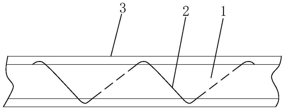
[0021] See figure 1 As shown, a flexible optical fiber cable of the present invention includes a core 1, an optical fiber layer located outside the core 1, and a protective layer 3 located outside the optical fiber layer. The optical fiber layer is formed by spirally winding a wire 2 outside the core 1. The wire 2 is an optical fiber, or the wire 2 includes an optical fiber. When the wire 2 is an optical fiber, the number of the optical fiber may be one or several.

[0022] In this embodiment, the ratio of the winding pitch of the wire 2 to the diameter of the wire core 1 is 4.5˜20:1. Specifically, the winding pitch of the wire 2 is 10-30 mm, and the diameter of the wire core 1 is 1.5-4 mm. The outer diameter of the protective layer 3 is 2-10mm. For example, when the diameter of the wire core 1 is 4 mm, the winding pitch of the wire 2 is about 18 mm; when the diameter of the wire core 1 is 2 mm, the winding pitch of the wire 2 is about 20 mm; When it is 1.5mm, the winding ...

Embodiment 2

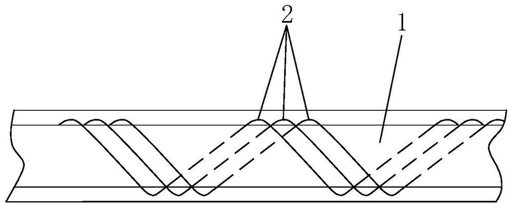
[0028] See figure 2 As shown, a flexible optical fiber cable of the present invention differs from the first embodiment above in that: the wires 2 are several, and the several wires 2 are wound side by side, so that it can solve the problem that one wire transmits multiple channels of different types. The problem of relatively inconvenient signals enables the present invention to connect multiple groups of different devices at the same time.


PUM

PropertyMeasurementUnit
diameteraaaaaaaaaa
diameteraaaaaaaaaa

Abstract

The invention discloses a flexible optical fiber cable which comprises a cable core, at least one optical fiber layer located outside the cable core and a protective layer located outside the optical fiber layer; the optical fiber layer is formed by spirally winding a wire outside the cable core, and the wire is an optical fiber or comprises an optical fiber. On one hand, the bending resistance of the optical fiber can be improved, the optical fiber is not easy to break when being bent; and on the other hand, the winding distance can be regulated, and the optical power loss of the optical fiber is ensured to be minimum.

Description

technical field [0001] The invention relates to the field of optical fiber communication, in particular to a flexible optical fiber line. Background technique [0002] Optical fiber communication has been widely used for its advantages of large information capacity, good confidentiality, light weight, small size, and long transmission distance, and it is widely used in communication, transportation, industry, medical care, education, aerospace, computer and other industries. The application of optical fiber is bringing profound impact and changes to human life. The flexible optical fiber in the prior art usually includes an optical fiber and a sheath outside the optical fiber. The bending radius (also called bending radius) of the flexible optical fiber is the bending radius of the optical fiber. It is generally recommended to be about 30 mm. However, in In practical applications, the bending radius of the flexible optical fiber cable by users or construction personnel is o...

Claims


Application Information

Patent Timeline
Patent Type & Authority Applications(China)
IPC IPC(8): G02B6/44
CPCG02B6/4413G02B6/4429G02B6/443G02B6/4434
Inventor 林洪沂刘虹穆瑞珍董志鹏孙栋张仕华吴隆清
Owner 龙岩岳凯科技有限公司
Why Eureka
Try Eureka