
Mine electric locomotive common-mode voltage prediction control method based on voltage vector

A technology of voltage vector and common mode voltage, which is applied in motor generator control, electronically commutated motor control, motor control, etc., can solve the problems of large amount of calculation, high switching loss, large current ripple, etc., and achieve simple control, The effect of reducing calculation pressure and reducing output current ripple

Active Publication Date: 2021-06-22
CHINA UNIV OF MINING & TECH
View PDF6 Cites 1 Cited by
  • Summary
  • Abstract
  • Description
  • Claims
  • Application Information

AI Technical Summary

Problems solved by technology

The traditional common-mode voltage suppression method based on model predictive control directly removes the zero vector and only uses the effective vector action, which not only has large current ripple but also high switching loss, so some scholars have proposed some improved methods on this basis, such as patent document 201510724306.6 The disclosed suppression method of the permanent magnet synchronous motor model based on the two-level inverter considers the switching loss, but still only uses the effective vector to act, resulting in excessive current ripple; one disclosed in patent document 201810688149.1 The common-mode voltage suppression method of the voltage source inverter model prediction takes the current ripple problem into consideration, and takes the zero vector as the candidate vector, but due to the optimization process of the value function, the calculation amount is large

Method used


Image

  • Mine electric locomotive common-mode voltage prediction control method based on voltage vector
  • Mine electric locomotive common-mode voltage prediction control method based on voltage vector
  • Mine electric locomotive common-mode voltage prediction control method based on voltage vector

Examples


Embodiment Construction

[0049] The present invention will be further described in detail below in conjunction with the accompanying drawings and specific embodiments.

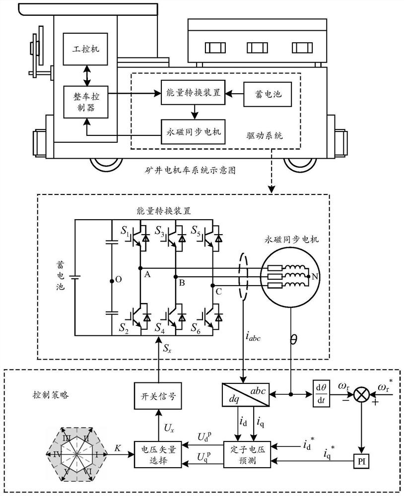
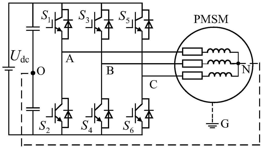
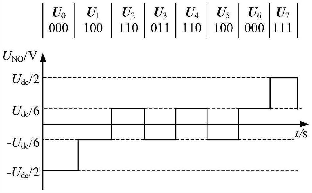
[0050] figure 1 It is the general schematic diagram of the mine electric locomotive drive system, figure 2 Topological diagram of the main circuit, the main circuit includes a battery, a three-phase two-level voltage source inverter, and a permanent magnet synchronous motor. The DC output voltage of the battery is constant, and the voltage is U dc ; Point O is the midpoint of the DC bus, point G is the grounding point of the permanent magnet synchronous motor casing, and point N is the neutral point of the permanent magnet synchronous motor. The system output common-mode voltage is defined as U NG =U NO + U OG , U NO is the potential between the neutral point of the motor load and the midpoint of the DC bus, U OG is the potential between the midpoint of the DC bus and the ground point of the motor case. But U OG relative to ...


PUM


Abstract

The invention discloses a mine electric locomotive common-mode voltage prediction control method based on a voltage vector, and the method comprises the steps of converting a current prediction process into a voltage prediction process, and carrying out re-division on an existing space voltage vector sector generated by a three-phase two-level voltage source inverter, on the basis of the newly divided sectors, subdividing the sectors into a zero vector selection area and an effective vector selection area; and finally, according to different working conditions of the mine electric locomotive, selecting a proper common-mode voltage suppression coefficient to adjust the proportion of the two selected areas. According to the present invention, under the condition that the common-mode voltage suppression effect is met, output current ripples are effectively reduced; the method is simple in design and flexible in control, effectively solves the problem of large output current ripples in an existing common-mode voltage suppression method, and reduces the model prediction control calculation amount by using the newly divided sectors; while the common-mode voltage of a driving system of a mine electric locomotive is suppressed, current ripples output by the driving system are reduced, so that the operation of the electric locomotive is more stable.

Description

technical field [0001] The invention relates to a method for predicting and controlling the common-mode voltage of mine electric locomotives, in particular to a method for predicting and controlling the common-mode voltage of mine electric locomotives based on voltage vectors. Background technique [0002] In recent years, due to the advantages of simple structure, convenient operation, high safety factor, low noise, and stable operation, mine electric locomotives have been widely used in the production and transportation of mines, and they are indispensable core transportation equipment for coal mine production operations. The drive system of mine electric locomotive mainly includes three parts: battery, energy conversion device and motor load, among which the energy conversion device is the core link of the drive system, and the inverter based on power electronic devices is an important unit in the energy conversion device. The quality of performance is the key factor to e...

Claims


Application Information

Patent Timeline
Patent Type & Authority Applications(China)
IPC IPC(8): H02P21/22H02P21/14H02P21/05H02P6/10H02P6/28H02P25/024H02P27/08
CPCH02P21/22H02P21/14H02P21/05H02P6/10H02P6/28H02P25/024H02P27/08H02P2207/05
Inventor 李小强谢淼朱真才张益东吴富强纪明理伍小杰
Owner CHINA UNIV OF MINING & TECH
Learn More