An amphibious wheel groove drainage drag reduction, anti-sway device and amphibious vehicle

A technology of drag reduction device and amphibious vehicle, which is applied in amphibious vehicles, motor vehicles, transportation and packaging, etc., and can solve the problems of water tightness, corrosion resistance and power efficiency of amphibious vehicles, heavy weight and poor reliability of the drag reduction mechanism, etc. problems, to achieve the effect of improving stability, reducing total resistance, and high reliability

Active Publication Date: 2022-07-26
NAT UNIV OF DEFENSE TECH
View PDF0 Cites 0 Cited by
  • Summary
  • Abstract
  • Description
  • Claims
  • Application Information

AI Technical Summary

Problems solved by technology

[0003] The existing amphibious wheel groove drag reduction technology uses iron sheets to wrap the bottom of the vehicle. The drag reduction mechanism is heavy, complicated to implement, and poor in reliability, and it will affect the water tightness, corrosion resistance and power efficiency of the amphibious vehicle.

Method used


Image

  • An amphibious wheel groove drainage drag reduction, anti-sway device and amphibious vehicle
  • An amphibious wheel groove drainage drag reduction, anti-sway device and amphibious vehicle
  • An amphibious wheel groove drainage drag reduction, anti-sway device and amphibious vehicle

Examples


Embodiment 1

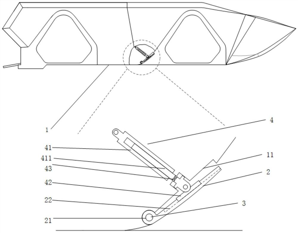
[0030] An amphibious wheel groove drainage and drag reduction device, such as figure 1 As shown, the amphibious vehicle body 1 is included, and a drainage plate 2 is installed on the rear side walls of the wheel grooves located in the front on both sides of the amphibious vehicle body 1. The lower end of the drainage plate 2 is provided with a through hole 21. Rotatingly connected at the bottom of the rear side wall of the wheel groove, the guide plate 2 pushes the guide plate 5 to rotate around the rotating part 3 through the angle adjustment device 4 to adjust the angle between the guide plate 2 and the bottom surface of the amphibious vehicle. When driving in water, the guide plate 2 is at the waterline. In this embodiment, by using the position of the rear triangle of the two wheel grooves in front of the amphibious vehicle, a guide plate 2 is installed on the rear side wall of the wheel groove, and the angle of the guide plate is adjusted by the included angle adjustment ...

Embodiment 2

[0036] The difference between this embodiment and the first embodiment is that the angle adjustment device is different. In this embodiment, the included angle adjustment device includes a hydraulic push rod installed in the amphibious vehicle body, and the upper end of the hydraulic push rod is connected to the amphibious vehicle body. Fixed connection, the telescopic rod of the hydraulic push rod protrudes out of the amphibious vehicle body, a sealing ring is installed at the contact point between the telescopic rod and the amphibious vehicle body, and the top of the telescopic rod is equipped with a The inner side of the guide plate is a roller that rolls longitudinally. When the telescopic rod is stretched, the roller is driven to roll up and down on the guide plate to adjust the angle between the guide plate and the bottom surface of the amphibious vehicle. The slider in the first embodiment is replaced with a roller, and the top end of the telescopic rod on the hydraulic ...

Embodiment 3

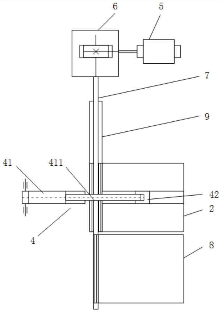
[0038] The difference between this embodiment and the previous two embodiments is that the hydraulic push rod 41 and the slider 42 are replaced by a motor and a reducer, and the pin shaft is replaced by a rotating shaft, and the rotation of the drainage plate 2 is directly driven by the motor reducer, specifically: The included angle adjusting device 4 includes a motor and a reducer arranged in the amphibious vehicle body, the rotating component 3 is a rotating shaft, the rotating shaft extends out of the amphibious vehicle body, and the rotating shaft is connected to the amphibious vehicle. A sealing ring is installed at the contact part of the body to prevent water seepage into the vehicle body at the contact part. The outer side of the rotating shaft and the inner side of the through hole are provided with cooperating splines, and the rotating shaft and the drainage plate 2 are fixedly connected by splines. , the reducer is connected with the rotating shaft, and the motor dr...


PUM


Abstract

The invention provides an amphibious wheel groove drainage drag reduction and anti-sway device and an amphibious vehicle. By using the position of the rear triangle of the two wheel grooves in front of the amphibious vehicle, a drainage plate is installed at the rear side of the wheel groove, and the The angle adjustment device adjusts the angle of the guide plate to change the inflow angle and the angle of the pressure wave, thereby reducing the resistance of the whole vehicle. The invention can reduce the inflow angle at the fault and the wave-making height by installing the diversion plate, so as to reduce the wave-making resistance and the viscous pressure resistance of the amphibious vehicle, thereby reducing the total resistance of the amphibious vehicle sailing on water. The test shows that the highest resistance reduction The effect can reach 26.32%. The invention has the advantages of simple structure, small occupied space, little influence on the weight of the whole vehicle, high reliability and easy realization. The anti-roll device is integrated on the basis of the drag-reduction device, which saves space, and because the drag-reduction device and the anti-roll device move independently, they do not affect each other, which improves the smooth sailing effect of the amphibious vehicle in water.

Description

technical field [0001] The invention belongs to the field of amphibious vehicles, and in particular relates to an amphibious wheel groove drainage and drag reduction and anti-rolling device and an amphibious vehicle. Background technique [0002] Compared with ships, amphibious vehicles have special shapes and structures, resulting in greater resistance in the water. In order to take into account the driving system on the road, amphibious vehicles are generally provided with wheel grooves at the running mechanism, which destroys the continuity and streamline of the surface and generates a large amount of additional resistance. If measures can be taken to reduce the influence of the fault at the amphibious wheel groove, especially the influence of the fault at the first wheel groove, the water driving resistance of the amphibious vehicle can be effectively reduced. [0003] The existing amphibious wheel groove drag reduction technology uses iron sheets to wrap the entire bot...

Claims


Application Information

Patent Timeline
Patent Type & Authority Patents(China)
IPC IPC(8): B60F3/00B63B1/40B63B39/06
CPCB60F3/00B60F3/0046B63B1/40B63B39/06Y02T70/10
Inventor 潘迪博刘博龙徐小军徐海军
Owner NAT UNIV OF DEFENSE TECH
Why Eureka
Try Eureka