
Automobile headlamp cleaning structure

A technology of automobiles and nozzles, which is applied in the field of automobile parts, can solve the problems of less configuration, complex mechanism and high cost, and achieve the effect of simple structure, easy maintenance and reduced manufacturing cost

Inactive Publication Date: 2021-06-25
HEFEI CHANGAN AUTOMOBILE
View PDF11 Cites 0 Cited by
  • Summary
  • Abstract
  • Description
  • Claims
  • Application Information

AI Technical Summary

Problems solved by technology

[0003] In recent years, the automobile industry has developed rapidly. With the increase in car ownership, car configuration functions have become more and more abundant. In the past, relatively high-end configurations have become more and more accessible to the people. However, headlight cleaning configurations generally appear on imported models or higher-end models of joint venture vehicles. Above, the more common built-in type, that is, it is hidden inside the bumper under the headlight when it is not in use. When in use, the headlight cleaning mechanism will stretch and open the bumper cover cover, and the angle of the headlight cleaning nozzle is aligned with the outer lens of the headlight. Spray cleaning liquid, reach the purpose of cleaning, for example Chinese invention patent publication number is that CN110053587A discloses a kind of automobile headlight washer, and Chinese utility model patent publication number is that CN203902497U discloses a kind of headlight cleaning device and automobile, all discloses hidden Although the above-mentioned hidden cleaning appliances have the advantages of high beauty and concealment, the mechanism is complicated and the cost is very high, and generally low-cost models are rarely equipped.

Method used


Image

  • Automobile headlamp cleaning structure
  • Automobile headlamp cleaning structure
  • Automobile headlamp cleaning structure

Examples


Embodiment Construction

[0029] In order to facilitate those skilled in the art to understand the technical solution of the present invention, the technical solution of the present invention will be further described in conjunction with the accompanying drawings.

[0030] In this application, terms such as "installation", "connection", "connection" and "fixation" should be interpreted in a broad sense, for example, it can be a fixed connection or a detachable connection, unless otherwise clearly specified and limited. , or integrated; it can be a mechanical connection, an electrical connection, or a communication; it can be a direct connection or an indirect connection through an intermediary, it can be the internal communication of two components or the interaction relationship between two components . Those of ordinary skill in the art can understand the specific meanings of the above terms in this application according to specific situations.

[0031] In this application, unless otherwise clearly ...


PUM


Abstract

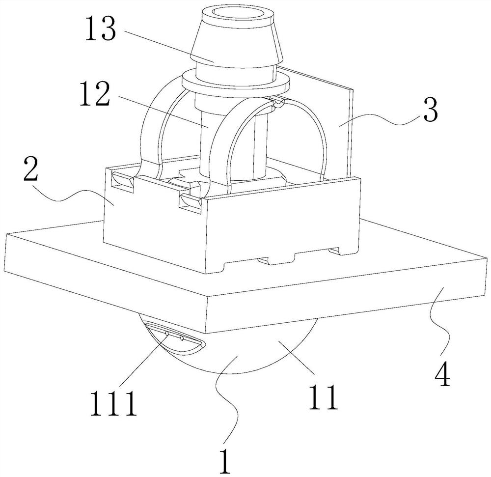
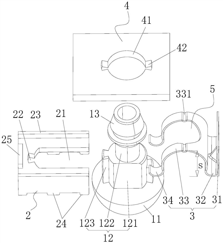
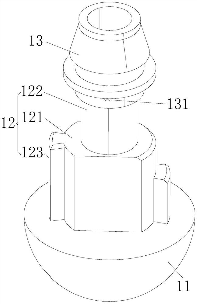
The invention discloses an automobile headlamp cleaning structure which comprises a nozzle, a support and an elastic piece. The nozzle comprises a nozzle round head, a connecting rod and a hoop structure, a spray head is arranged on the nozzle round head, the input end of the nozzle round head is connected with the hoop structure through the connecting rod, the nozzle round head is arranged close to the outer wall of the automobile bumper skin, the connecting rod and the hoop structure are arranged close to the inner wall of the automobile bumper skin, the connecting rod is connected with the automobile bumper skin in a clamped and matched mode, the support is connected with the connecting rod in a clamped mode, the elastic piece is connected between the support and the hoop structure in a clamped mode and abuts against the elastic piece, so that the support is tightly attached to the inner wall of the automobile bumper skin, and then the nozzle round head and the support are tightly attached to the outer wall and the inner wall of the automobile bumper skin. The automobile headlamp cleaning structure has the advantages that the structure is simple, the nozzle round head only needs to be arranged outside an automobile, disassembly, assembly and maintenance are easy, and the manufacturing cost is greatly reduced.

Description

technical field [0001] The invention relates to the technical field of automobile parts, in particular to an automobile headlight cleaning structure. Background technique [0002] The headlight washer is a functional part of the car located near the headlights of the car. Its main function is to spray cleaning fluid from the headlight cleaning mechanism to clean the headlights in time when the headlights are dirty. [0003] In recent years, the automobile industry has developed rapidly. With the increase in car ownership, car configuration functions have become more and more abundant. In the past, relatively high-end configurations have become more and more accessible to the people. However, headlight cleaning configurations generally appear on imported models or higher-end models of joint venture vehicles. Above, the more common built-in type, that is, it is hidden inside the bumper under the headlight when it is not in use. When in use, the headlight cleaning mechanism wil...

Claims


Application Information

Patent Timeline
Patent Type & Authority Applications(China)
IPC IPC(8): B60S1/56B60S1/52
CPCB60S1/56B60S1/52
Inventor 潘继军周勇杨志莹邱元苠
Owner HEFEI CHANGAN AUTOMOBILE
Learn More