Air-locking discharging device

A technology of unloading device and air lock, which is applied in the direction of transportation, packaging, loading/unloading, etc., can solve the problems of uncontinuous feeding, coal consumption, power consumption increase, restrictions on continuous release of hazardous waste and air lock, etc., to achieve Avoid health risks and safety risks, improve stability and safety, and realize the effect of automatic continuous feeding

Pending Publication Date: 2021-06-25
广灵金隅水泥有限公司
View PDF15 Cites 0 Cited by
  • Summary
  • Abstract
  • Description
  • Claims
  • Application Information

AI Technical Summary

Problems solved by technology

When disposing of hazardous waste, there are distillation residues, bulk sludge, waste salt, paint residue, waste activated carbon, spinning waste, waste rags, PPE, waste medicine bottles, waste oil barrels, etc., which are sticky, lumpy, and corrosive The characteristic hazardous waste cannot be added from other feeding ports such as semi-solid, and can only be put into the kiln tail smoke chamber from the manual feeding port for treatment
However, there is no suitable air lock device at the manual feeding port, and the air leakage is serious. The air leakage problem not only affects the normal operation of the cement kiln system, but also causes an increase in coal consumption and power consumption.
[0004] Existing air lock designs usually use rotary valves, block valves, flap valves, pinch valves, pneumatic double valve plates, high-temperature air lock valves, three-way air lock valves, etc., but none of them can completely solve the air leakage problem, especially for For hazardous waste with complex and diverse forms and structures, the above-mentioned air lock designs are not well applicable, and there are defects such as material blockage, equipment jamming, many faults, and inability to continuously feed materials, which seriously restrict the continuous delivery and operation of hazardous waste. Wind lock problem

Method used


Image

  • Air-locking discharging device
  • Air-locking discharging device
  • Air-locking discharging device

Examples


Embodiment Construction

[0029] The present invention is described below based on examples, but the present invention is not limited to these examples. In the following detailed description of the invention, some specific details are set forth in detail. The present invention can be fully understood by those skilled in the art without the description of these detailed parts. To avoid obscuring the essence of the present invention, well-known methods, procedures, procedures, and components have not been described in detail.

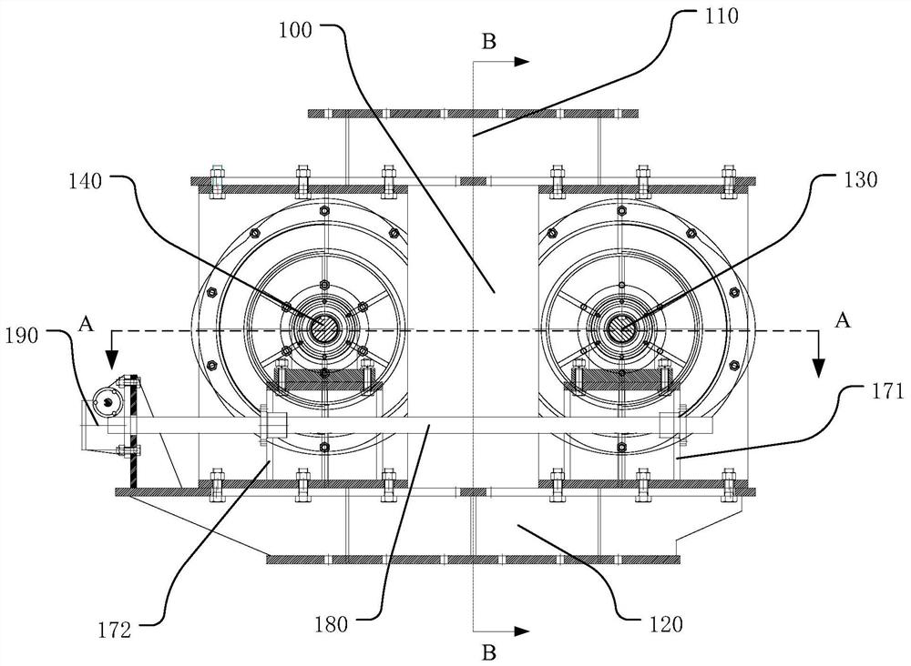
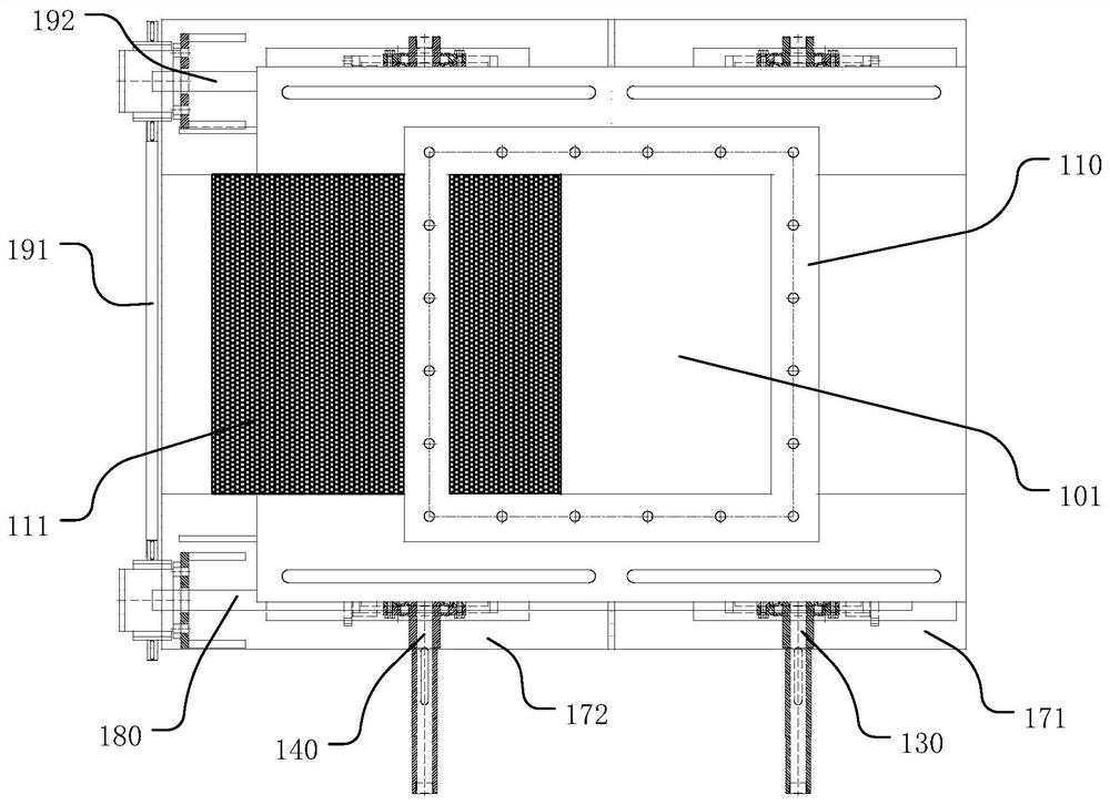
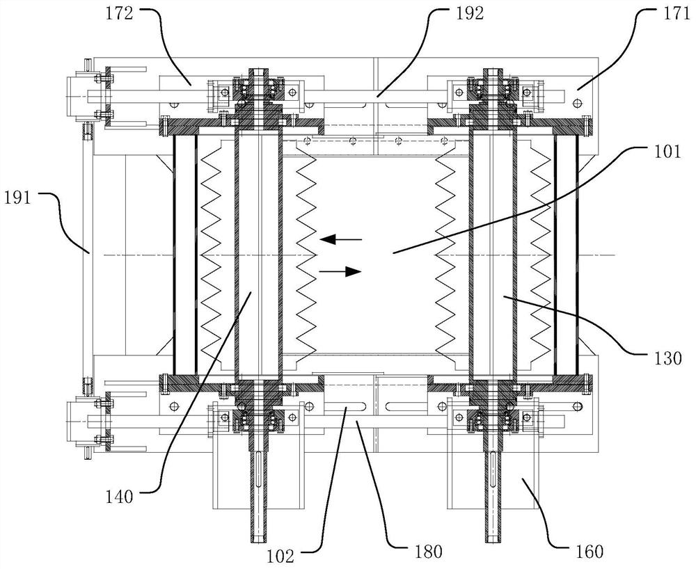
[0030] figure 1 and figure 2 A schematic diagram and a top view of the wind lock and discharge device according to the embodiment of the present invention are respectively shown. The windlock discharge device includes a main body 100 , a first discharge roller 130 , a second discharge roller 140 , a first support frame 171 , a second support frame 172 , an adjusting screw 180 and a synchronous structure 190 . Wherein, the main body 100 includes a cavity 101 for accommodating ...


PUM


Abstract

The invention discloses an air-locking discharging device which mainly solves the problems of air leakage, material blockage and the like in an existing discharging device. The air-locking discharging device comprises a main body, a first discharging roller, a second discharging roller and an adjusting screw rod. The main body is provided with a cavity used for containing materials, the first discharging roller and the second discharging roller are both located in the main body, and the two ends of the first discharging roller and the two ends of the second discharging roller penetrate out of the main body and are further supported by a supporting frame. The second unloading roller is parallel to the first unloading roller. The adjusting screw rod is connected with the supporting frame of the first discharging roller and the supporting frame of the second discharging roller, the distance between two supporting pieces can be adjusted by rotating the adjusting screw rod, and therefore the gap between the first discharging roller and the second discharging roller is adjusted so as to be adapted to the materials with different particle sizes and viscosities. According to the air-locking discharging device provided by the invention, the problem of air leakage is reduced. And continuous and automatic feeding of materials can be achieved, the labor cost is reduced, and the safety and stability of equipment are improved.

Description

technical field [0001] The invention relates to the field of hazardous waste treatment, in particular to an air lock unloading device. Background technique [0002] With the rapid development of the national social economy, the industry has also developed rapidly, and the production and consumption of more and more industrial products, chemical products and other products have also increased sharply. Some products or semi-finished products are corrosive and flammable. , Toxicity to the human body and other dangerous properties, before transportation and transfer, it needs to be packaged and sealed in corresponding packaging containers. After the service life of this type of packaging container is reached, the packaging container cannot be recycled as ordinary waste due to its contamination or residue of corresponding products. Discarded waste packaging, containers, filter and adsorption media and other wastes are treated as hazardous wastes, and iron hazardous waste packagi...

Claims


Application Information

Patent Timeline
Patent Type & Authority Applications(China)
IPC IPC(8): B65G65/40
CPCB65G65/40
Inventor 郭伍李胜保邢磊郭建军赵树海郄富家兴成林
Owner 广灵金隅水泥有限公司
Why Eureka
Try Eureka