Calcinating shaft kiln comprehensively utilizing heat energy unit temperature field

A temperature field and roasting technology, applied in the field of shaft kiln, can solve the problems of low product quality, small roasting area, large single-machine production capacity, etc., and achieve the effect of uniform airflow distribution, small roasting area, and large single-machine production capacity

Inactive Publication Date: 2013-06-12
鞍山市华杰石灰工业设计研究有限公司
View PDF1 Cites 0 Cited by
  • Summary
  • Abstract
  • Description
  • Claims
  • Application Information

AI Technical Summary

Problems solved by technology

[0016] The purpose of the present invention is to provide a comprehensive utilization of thermal energy unit temperature field roasting shaft kiln, which solves the common technical problems of low product quality and high heat consumption in existing shaft kilns. Compared with similar equipment, its structure design is reasonable and material distribution , The air flow is evenly distributed; the preheating, roasting, and cooling processes can be precisely controlled; the roasting area of ​​each unit temperature field is small, the flame jet penetrating power is strong, and the temperature distribution in the field is uniform, with good product quality, large single-machine production capacity, and low heat consumption. Etc

Method used


Image

  • Calcinating shaft kiln comprehensively utilizing heat energy unit temperature field
  • Calcinating shaft kiln comprehensively utilizing heat energy unit temperature field
  • Calcinating shaft kiln comprehensively utilizing heat energy unit temperature field

Examples


Embodiment Construction

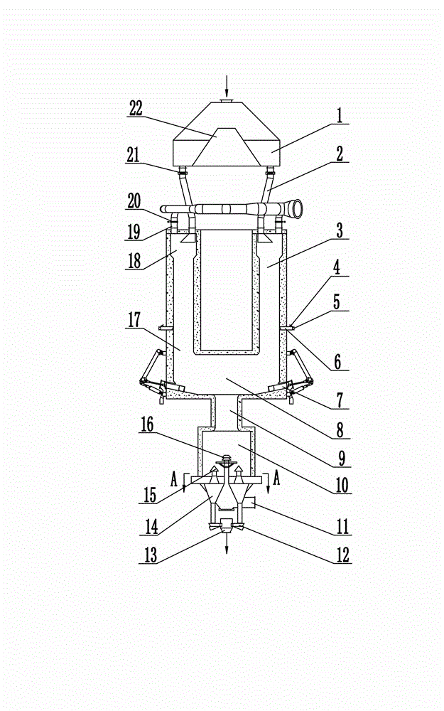
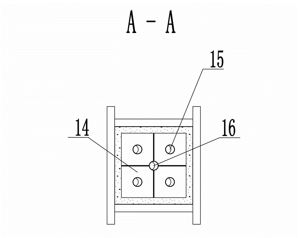
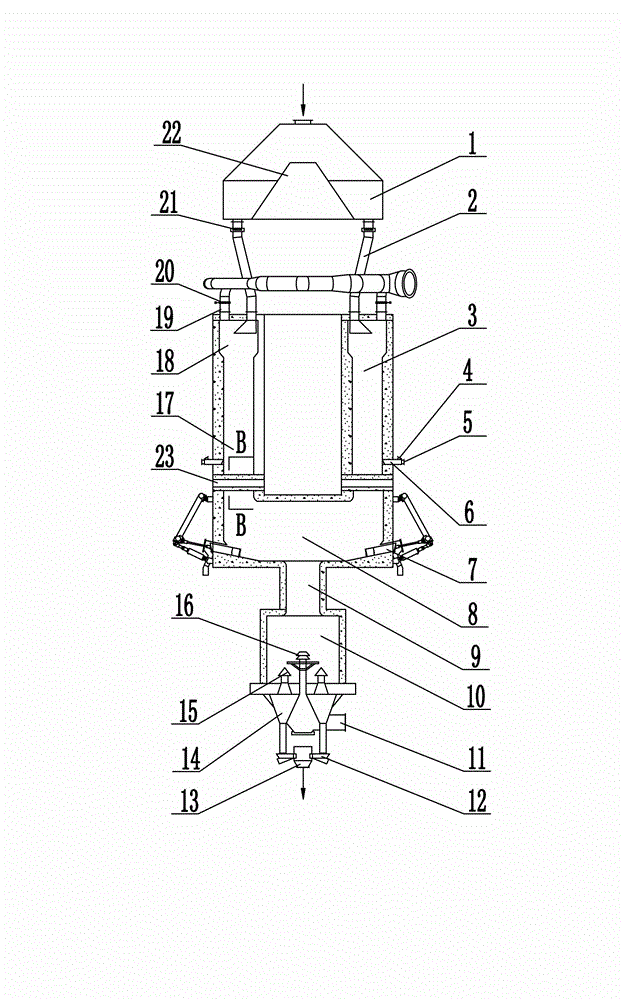
[0044] Combine below Figure 1~4 Specific embodiments of the present invention will be described in detail. The temperature field roasting shaft kiln for comprehensive utilization of thermal energy includes a feeding bin, a feeding pipe, a roasting chamber and a cooling chamber, wherein the specification and shape of the ring channel diverting feeding bin 1 arranged on the top of the shaft kiln should be selected according to actual use needs. The feed distribution cone 22 is set in the feed bin 1 of the ring channel diversion, so that the material in the feed bin is evenly distributed in the loop between the feed bin wall and the feed feed cone 22 through the feed distribution cone 22, and is respectively connected with each feeding lock air pipe 2 The discharge ports are symmetrically and evenly distributed along the ring road at the bottom of the silo. Using the peripheral unloading method, the materials in the silo are evenly distributed directly above the feeding lock ai...


PUM


Abstract

The invention provides a calcinating shaft kiln comprehensively utilizing heat energy unit temperature field and solves the problems of the existing shaft kiln that product quality is low and heat consumption is high. The calcinating shaft kiln comprises a feeding bin, a feeding pipe, a calcinating chamber and a cooling chamber. According to the technical key points of the invention, each discharge port of a top loop shunting feeding bin is connected with the feed inlet of the respective independent unit temperature field material calcinating activate chamber through a feed air lock pipe; each chamber is internally provided with one unit temperature field combustor, the bottom of each chamber is communicated with a material integrative energy integration chamber, and is communicated with the proportion gas flow strengthening cooling chamber through a material diffusing heat exchange region, the lower part of the balance gas flow strengthening cooling chamber provided with a center cooling nozzle button and a chamber cooling nozzle button is connected with the discharging air lock device. The calcinating shaft kiln has reasonable structure design, and can be controlled accurately in material preheating, calcination and cooling process; each unit temperature field has the advantages of small calcinating region, strong flame ejection penetrating power, uniform temperature distribution in the temperature field, good product quality and low heat rate.

Description

technical field [0001] The patent of the invention relates to a shaft kiln for roasting massive materials, especially a kind of kiln for roasting limestone, dolomite, magnesite, bauxite and other massive materials with large roasting area and high production capacity, which is beneficial to realize automatic control Comprehensive utilization of thermal energy unit temperature field roasting shaft kiln. Background technique [0002] In recent years, various types of shaft kilns have been greatly improved in structure and operation in this technical field. For example: the vertical kiln develops from a single chamber to a double chamber structure (Maerz kiln); the arrangement of the burner develops from the peripheral setting to the peripheral combined with the central setting or along the material flow; the unloading structure develops from the spiral cone to the supporting plate structure; The material and unloading operations have been mechanized and automated. [0003] A...

Claims


Application Information

Patent Timeline
Patent Type & Authority Patents(China)
IPC IPC(8): F27B1/02F27B1/10F27B1/26F27B1/24F27B1/21
Inventor 蔺德中刘显龙孙士东
Owner 鞍山市华杰石灰工业设计研究有限公司
Why Eureka
Try Eureka