
Method and equipment for bubble blowing and tube breaking in glass capillary tube

A glass capillary and capillary technology, which is applied in glass manufacturing equipment, glass forming, glass reshaping, etc., can solve the problems of low production efficiency, waste of materials, and high labor intensity, and achieve high production efficiency and high forming size. Good consistency and good consistency of broken tube length

Active Publication Date: 2021-06-25
SOUTHEAST UNIV
View PDF6 Cites 0 Cited by
  • Summary
  • Abstract
  • Description
  • Claims
  • Application Information

AI Technical Summary

Problems solved by technology

[0003] The current method is to chamfer the inner hole of the joint fittings. It is to manually seal one end of the capillary with a flame, pass a certain pressure gas into the capillary, heat the end with a flame and bubble, and then mechanically remove the bulb. Leave the tail of the bulb as the chamfer of the inner hole of the capillary to facilitate the penetration of the optical fiber. This method of processing the capillary is labor-intensive, low in production efficiency, and wastes a lot of materials

Method used


Image

  • Method and equipment for bubble blowing and tube breaking in glass capillary tube
  • Method and equipment for bubble blowing and tube breaking in glass capillary tube
  • Method and equipment for bubble blowing and tube breaking in glass capillary tube

Examples


Embodiment Construction

[0061] The present invention will be further explained below in conjunction with the accompanying drawings and specific embodiments. It should be understood that the following specific embodiments are only used to illustrate the present invention but not to limit the scope of the present invention.

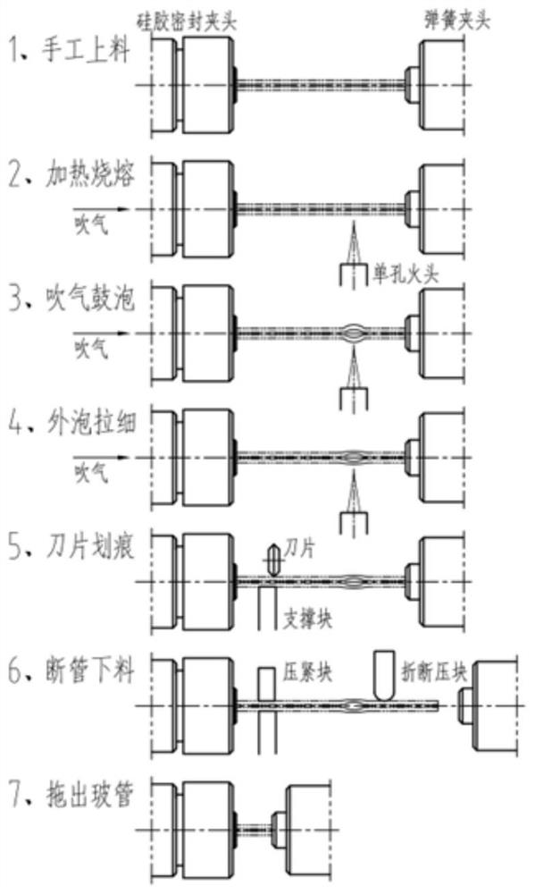
[0062] Step 1: The whole glass capillary is manually loaded in the left end chuck body, the right end of the capillary is clamped by the right end chuck, the capillary is pulled out from the left end chuck body, and the capillary is clamped by the two end chucks.

[0063] Step 2: The capillary rotates with the chucks at both ends, and the single-hole burner ignites the flame to melt the capillary.

[0064] Step 3: A certain pressure gas is introduced into the capillary, and the melting part bubbles into an ellipsoid.

[0065] Step 4: The capillary continues to be heated, the chuck at the right end moves to the right, and the bulb is stretched. The wall thickness of the outer diam...


PUM


Abstract

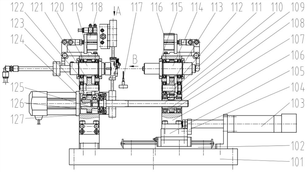
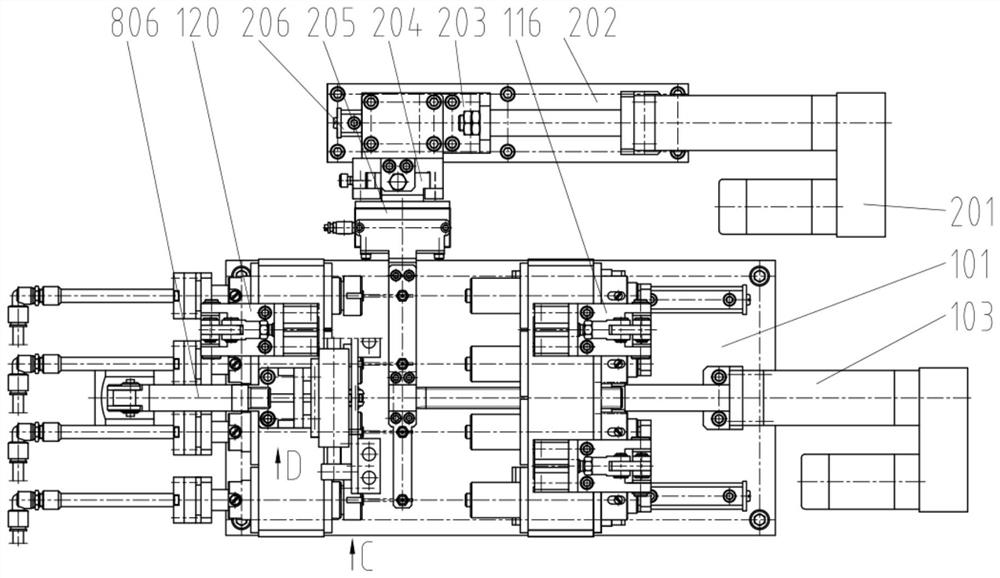
The invention discloses a method and equipment for bubble blowing and tube breaking in a glass capillary tube. The equipment comprises a left end chuck assembly, a right end chuck assembly, a right end chuck body moving mechanism, a fire head assembly, a fire head moving mechanism, a capillary tube supporting block mechanism, a capillary tube scratching mechanism, a capillary tube breaking mechanism and a synchronous rotating mechanism capable of promoting the left end chuck assembly and the right end chuck assembly to rotate synchronously. The left end chuck assembly is used for clamping the capillary tube through contraction of sealing colloidal particles, and a rotating joint is arranged at the tail part of the left end chuck assembly so as to carry out air inlet bubbling on the clamped capillary tube. The right end chuck assembly clamps the capillary tube in the mode that an inner hole is contracted through a spring chuck. The capillary tube scratching mechanism comprises a capillary tube supporting block, a scratching driving mechanism and a capillary tube scratching blade connected with the transmission end of the scratching driving mechanism. According to the invention, automatic bubble blowing and pipe breaking processing can be realized, multiple groups can be arranged side by side for simultaneous processing, the production efficiency is improved, the labor intensity of workers is reduced, and the quality consistency is good.

Description

technical field [0001] The invention relates to a processing transition process for optical fiber joint fittings, which is a method and equipment for blowing bubbles in a glass capillary and breaking the tube, and belongs to the technical fields of optical fiber fitting processing and quartz glass processing. Background technique [0002] In the production process of optical fiber joints, the optical fiber should be inserted into the joint fittings. The joint fittings are glass capillary tubes with a hole diameter matching the outer diameter of the optical fiber, and the glass capillary tubes are drawn from large-diameter glass tubes. The dimensions are equal in diameter, and due to the small diameter of the optical fiber, it is difficult to manually insert it into a connector fitting with a matching bore. [0003] The current method is to chamfer the inner hole of the joint fittings. It is to manually seal one end of the capillary with a flame, inject a certain pressure gas...

Claims


Application Information

Patent Timeline
Patent Type & Authority Applications(China)
IPC IPC(8): C03B33/06C03B23/09
CPCC03B33/06C03B23/097Y02P40/57
Inventor 何荣开闻煜陈刚
Owner SOUTHEAST UNIV
Learn More