Automatic dredging system and method for converter vaporization flue sampling hole

A vaporization flue and sampling hole technology, which is used in the manufacture of converters and other directions, can solve the problems of bad working conditions of the vaporization flue, clogging of the sampling hole of the detection device, and difficulty in stable and reliable cleaning, so as to reduce the maintenance amount and prolong the service life. , the effect of simple structure

Active Publication Date: 2021-06-25
CHINA NAT HEAVY MACHINERY RES INSTCO
View PDF3 Cites 0 Cited by
  • Summary
  • Abstract
  • Description
  • Claims
  • Application Information

AI Technical Summary

Problems solved by technology

[0003] The purpose of the present invention is to overcome the deficiencies of the above-mentioned prior art, and provide an automatic dredging system and dredging method for the sampling hole of the converter vaporization flue, which overcomes the poor working conditions in the vaporization flue in the prior art, and the detection of pressure etc. The sampling hole of the device is often blocked, and the current conventional nitrogen and other purging devices are difficult to clean up stably and reliably

Method used


Image

  • Automatic dredging system and method for converter vaporization flue sampling hole
  • Automatic dredging system and method for converter vaporization flue sampling hole

Examples


specific Embodiment approach

[0028] It should be noted that the structures, proportions, sizes, etc. shown in this specification are only used to cooperate with the content disclosed in the specification for the understanding and reading of those familiar with this technology, and are not used to limit the conditions for the implementation of the present invention , any modification of structure, change of proportional relationship or adjustment of size shall still fall within the scope covered by the technical content disclosed in the present invention without affecting the effect and purpose of the present invention. .

[0029] At the same time, terms such as "upper", "lower", "left", "right", "middle" and "one" quoted in this specification are only for the convenience of description and are not used to limit this specification. The practicable scope of the invention and the change or adjustment of its relative relationship shall also be regarded as the practicable scope of the present invention without...

Embodiment 1

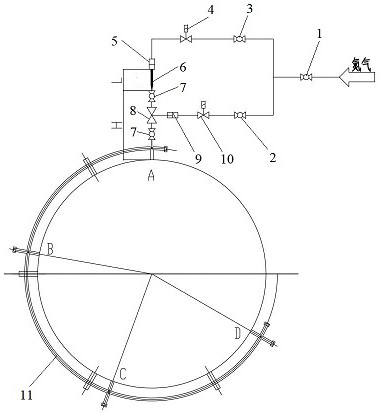
[0031] like figure 1 As shown, the present invention discloses an automatic dredging system for the sampling hole of the converter vaporization flue, including a valve group control pipeline, a dredger control pipeline, a sampling hole control valve group, a dredger 6 and a control assembly, the valve group One end of the control pipeline is connected to the nitrogen input pipeline, the other end of the valve group control pipeline is connected to the sampling hole control valve group, one end of the control pipeline of the dredger is connected to the nitrogen input pipeline, and the other end of the dredger control line is connected to the dredger 6, and the dredger control line is connected to the dredger 6. The silt 6 is opposite to the sampling hole control valve group, the sampling hole control valve group is connected to the sampling hole of the converter vaporization flue, and the dredger 6, the sampling hole control valve group and the converter vaporization flue sampli...

Embodiment 2

[0034] preferred, such as figure 1 As shown, the valve group control pipeline includes a valve group control manual valve 2, a second solenoid valve 10, and a second cylinder 9. One end of the valve group control manual valve 2 is connected to the nitrogen master valve 1 of the nitrogen input pipeline through a pipeline, and the valve group control The other end of the manual valve 2 is connected to the second solenoid valve 10 through a pipeline, and the other end of the second solenoid valve 10 is connected to the second cylinder 9 through a pipeline. The second cylinder 9 has a rod end connected to the sampling hole control valve group. The second solenoid valve 10 Electrically connected to the control assembly.

[0035] The valve group control manual valve 2 is generally in a normally open state. When the second solenoid valve 10 is in maintenance or maintenance, the valve group control manual valve 2 can be manually controlled to open and close.

[0036] The telescoping ...


PUM


Abstract

The invention discloses an automatic dredging system and method for a converter vaporization flue sampling hole. The automatic dredging system comprises a valve group control pipeline, a dredging device control pipeline, a sampling hole control valve group, a dredging device (6) and a control assembly. One end of the valve group control pipeline is connected with a nitrogen input pipeline, and the other end of the valve group control pipeline is connected with the sampling hole control valve group. One end of the dredging device control pipeline is connected with the nitrogen input pipeline, the other end of the dredging device control pipeline is connected with the dredging device (6), the dredging device (6) is opposite to the sampling hole control valve group in position, the sampling hole control valve group is connected with the converter vaporization flue sampling hole, and the dredging device (6), the sampling hole control valve group and the converter vaporization flue sampling hole are located on the same axis. The valve group control pipeline, the dredging device control pipeline and the nitrogen input pipeline are electrically connected with the control assembly.

Description

technical field [0001] The invention belongs to the technical field of dredging of a converter vaporization flue, and in particular relates to an automatic dredging system and a dredging method for a sampling hole of a converter vaporization flue. Background technique [0002] Oxygen converter steelmaking flue gas is one of the main air pollutants produced in the production process of the converter steelmaking industry. The coal gas and iron-containing dust in the converter flue gas must be recovered and utilized. Since the temperature of the converter steelmaking flue gas is as high as 1600 degrees, The first process after the converter flue gas is generated is to use the vaporization cooling flue to cool down, and at the same time to recover the steam generated by heat exchange. In order to increase the amount of gas recovery and effectively and accurately control the speed of the fan in the system, devices such as pressure sensing are often installed on the flue. Due to ...

Claims


Application Information

Patent Timeline
Patent Type & Authority Applications(China)
IPC IPC(8): C21C5/40C21C5/46
CPCC21C5/40C21C5/46
Inventor 李永辉李新强高璐吴量马莉莉李传东
Owner CHINA NAT HEAVY MACHINERY RES INSTCO
Why Eureka
Try Eureka