Improved structure of drum brake

A drum brake and a pair of technology, applied in the field of motorcycle and electric vehicle brake devices, can solve the problems of easy wear and tear of brake cams, poor braking effect of drum brakes, and large sliding distance of vehicle braking.

Pending Publication Date: 2021-06-25
申革英
View PDF0 Cites 0 Cited by
  • Summary
  • Abstract
  • Description
  • Claims
  • Application Information

AI Technical Summary

Problems solved by technology

[0003] The purpose of the present invention is to provide an improved structure of the drum brake, which changes the working mode of the original drum brake which uses the cam to directly drive the expansion of the brake shoe, and effectively improves the poor braking effect of the existing drum brake, the large sliding distance of the vehicle brake, and the large braking distance of the brake cam. Disadvantages of wear and tear
Compared with the original technology, the invention adopts the innovative structural design of using the brake rocker shaft to drive the gear and the tooth surface to rotate, and then drives the brake shoe to complete the brake, so that the operation of the brake mechanism is more labor-saving and the braking torque is increased. , The braking effect is better, and it also solves the problem that the original brake cam is easy to wear

Method used


Image

  • Improved structure of drum brake
  • Improved structure of drum brake

Examples


Embodiment

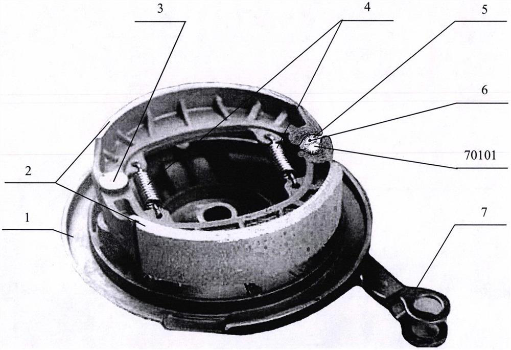
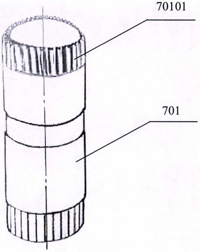
[0007] as attached figure 1 And attached figure 2 As shown, a pair of brake shoes (2) are installed in the housing (1), the elastic return element (4) is connected between the brake shoes (2), and one end of the pair of brake shoes (2) has a semicircle arc surface, and is installed on the rotating shaft (3), and can rotate around the rotating shaft (3). The rotating shaft (3) is fixedly installed on the casing (1). And the other end of a pair of brake shoes (2) is then made into concave toothed surface respectively, intermediate gear (5) and rocker shaft gear (70101) are installed between these two concave toothed surfaces. Among them, the intermediate gear (5) meshes with the toothed surface of one brake shoe (2) that it is in contact with, and the rocker shaft gear (70101) is also in contact with the toothed surface of the other brake shoe (2). The surfaces mesh with each other, and the intermediate gear (5) and the rocker shaft gear (70101) mesh with each other. The in...


PUM


Abstract

The invention provides an improved structure of a drum brake. A pair of brake shoes is installed in a drum brake shell, one end of each brake shoe is provided with a semicircular arc surface, the brake shoes are installed on a rotating shaft and can rotate around the rotating shaft, and the rotating shaft is fixedly installed on the drum brake shell. The other ends of the pair of brake shoes are each made into an inward-concave tooth-shaped surface, an intermediate gear and a rocker arm shaft gear are installed between the two tooth-shaped surfaces, and the intermediate gear is engaged with the tooth-shaped surface of one brake shoe in contact with the intermediate gear. The rocker arm shaft gear is also engaged with the tooth-shaped surface of the other brake shoe in contact with the rocker arm shaft gear. The intermediate gear is engaged with the rocker arm shaft gear, the intermediate gear is installed on the rotating shaft in a sleeving manner and can rotate around the rotating shaft, and the rotating shaft is also fixedly installed on the drum brake shell. The rocker arm shaft gear is a part of the structure of a rocker arm shaft of a brake rocker arm assembly. When the rocker arm shaft rotates, the pair of brake shoes can be driven to form opening and closing movement, and therefore the brake function is achieved.

Description

technical field [0001] The invention belongs to the technical field of brake devices for motorcycles and electric vehicles. Background technique [0002] Drum brakes have been used as brake components on motorcycles and electric vehicles for nearly a century. Their structure generally consists of a housing, a pair of brake shoes, a brake cam, a brake rocker arm, and elastic reset elements. When braking, the brake rocker arm drives the brake cam to rotate, and the brake cam forces the brake shoe to expand and contact the housing to generate friction and then brake. After braking, rely on the elastic return element to pull the brake shoe back to its original position. During the braking process, in addition to the wear between the brake shoe and the housing, there will also be wear between the brake cam and the brake shoe, and the wear is always concentrated on several points or surfaces of the brake cam, which greatly shortens the brake life. In addition, the existing drum ...

Claims


Application Information

Patent Timeline
Patent Type & Authority Applications(China)
IPC IPC(8): F16D51/22F16D65/14F16D121/14
CPCF16D51/22F16D65/14F16D2121/14
Inventor 申革英秦巍
Owner 申革英
Why Eureka
Try Eureka