
Lighting lamp

A technology of lighting fixtures and lighting beams, applied in the field of lighting, can solve problems such as wasting energy, consuming electric power, and not fully utilizing it, so as to achieve the effect of avoiding energy consumption and improving utilization

Pending Publication Date: 2021-06-25
SUPERVISION LASER TECH SUZHOU CO LTD
View PDF0 Cites 0 Cited by
  • Summary
  • Abstract
  • Description
  • Claims
  • Application Information

AI Technical Summary

Problems solved by technology

[0003] Existing LED far and near beam integrated automobile headlights usually comprise a low beam LED light source module, a high beam LED light source module, a light shield and a lens unit, and the low beam LED light source module and the high beam LED light source module emit The light is switched through the shading plate. The shading plate is usually made of electromagnet, but the use of electromagnet not only consumes electric power and wastes energy, but also the mechanical dimming mechanism is easy to cause malfunctions such as jamming
In addition, since the light emitted by the low-beam LED light source module is reflected by the low-beam reflector, it is mainly incident on the middle area of ​​the lens unit, and the areas on the left and right sides of the lens unit are not fully utilized, reducing the utilization rate of the lens unit

Method used


Image

  • Lighting lamp
  • Lighting lamp
  • Lighting lamp

Examples


Embodiment 1

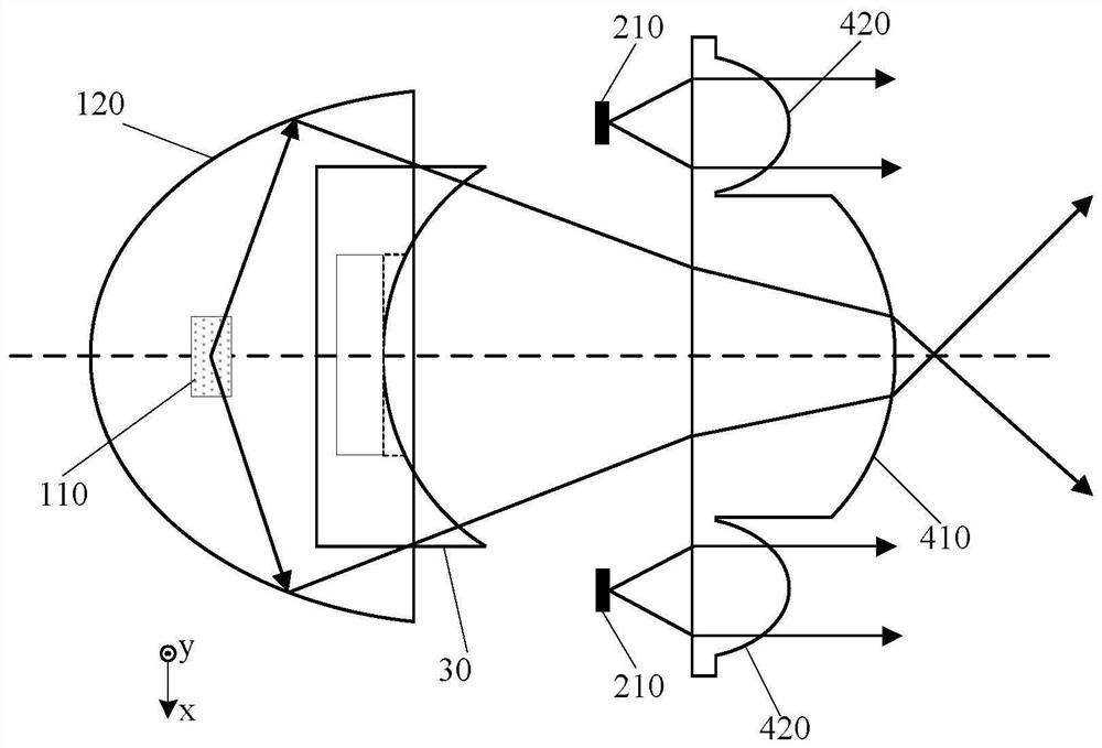
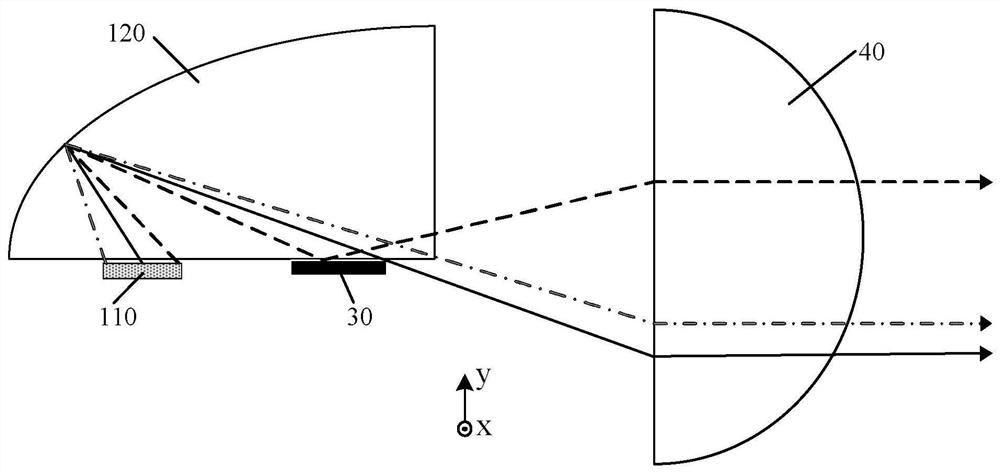
[0031] Such as Figure 1-2 As shown, the present invention provides a lighting fixture, which includes a first light source group 110 , a first reflective cup 120 corresponding to the first light source group 110 , a second light source group 210 and a lens unit 40 .

[0032] The first light source group 110 emits an illuminating beam, and the first reflective cup 120 collects the illuminating beam and reflects it along a specified direction. The first light source group 110 can be an LED light source or a laser light source, or a combination of an LED light source and a laser light source. The LED light source can be in the form of an LED chip and a phosphor sheet. The laser light source can be a laser diode or a semiconductor laser to remotely excite fluorescence. For the mode of the powder sheet, if a laser light source is used, it is necessary to open a light hole on the first reflector 120, so that the laser beam emitted by the laser diode or semiconductor laser is projec...

Embodiment 2

[0044] Such as Figure 8 As shown, the difference from Embodiment 1 is that the second light source group 210 includes a second LED light source 220 and a spherical reflective bowl 230 corresponding to the second LED light source 220, and the top of the spherical reflective bowl 230 is provided with The light outlet 231 , the position of the second LED light source 220 corresponds to the center of the spherical reflective bowl 230 . The light outlet 231 can be located in the middle of the top of the spherical reflective bowl 230, or can be located at a certain position on the side. A part of the light emitted by the second LED light source 220 is directly emitted from the light outlet 231 and projected to the second partition of the lens unit 40. After being collimated and emitted, another part of the light is reflected by the spherical reflective bowl 230 and then incident on the light-emitting surface of the second LED light source 220 to be excited again, and the above proc...


PUM

PropertyMeasurementUnit
Melting pointaaaaaaaaaa

Abstract

The invention discloses a lighting lamp which comprises a first light source set, a first reflection cup corresponding to the first light source set, a second light source set, a shading piece and a lens unit. The lens unit comprises a first subarea located in the middle and second subareas located on the two sides, and the first subarea and the second subareas have different focuses; light emitted by the first reflection cup is projected to the first subarea, and light emitted by the second light source group is projected to the second subarea. The lens unit has the first subarea in the middle and the second subareas located on the two sides, and light rays emitted by the first light source set are projected to the first subarea, light rays emitted by the second light source set are projected to the second subareas, so that the utilization rate of the lens unit can be greatly increased; and besides, the first light source set and the second light source set are controlled to be turned on and turned off through the control switch, so that switching between high-beam illumination and low-beam illumination is achieved, and the problems that energy is consumed and a machine is prone to being stuck when a traditional mechanical light changing mechanism is adopted are solved.

Description

technical field [0001] The invention relates to the field of lighting technology, in particular to a lighting fixture with integrated far and near light. Background technique [0002] With the development of semiconductor technology, LED (Light Emitting Diode, light-emitting diode) light source has the advantages of high efficiency, energy saving, environmental protection, low cost and long life, and is gradually replacing traditional incandescent lamps and energy-saving lamps, becoming a general lighting light source. [0003] Existing LED far and near beam integrated automobile headlights usually comprise a low beam LED light source module, a high beam LED light source module, a light shield and a lens unit, and the low beam LED light source module and the high beam LED light source module emit The light is switched through the shading plate. The shading plate is usually made of an electromagnet, but the use of an electromagnet not only consumes electric power and wastes ...

Claims


Application Information

Patent Timeline
IPC IPC(8): F21S41/25F21S41/30F21V23/04F21S41/141F21S41/143F21S41/147F21Y115/10F21W102/13
CPCF21V23/04F21Y2115/10F21S41/141F21S41/143F21S41/147F21S41/25F21S41/30F21W2102/13
Inventor 邹诚其他发明人请求不公开姓名
Owner SUPERVISION LASER TECH SUZHOU CO LTD
Learn More