
Test device for testing recovery efficiency of condensate on inner wall surface of nuclear power station containment vessel

A nuclear power plant containment and recovery efficiency technology, applied in the direction of measuring devices, electric devices, volume/mass flow generated by electromagnetic effects, etc., to achieve the effect of optimal design

Active Publication Date: 2021-06-25
SHANGHAI JIAO TONG UNIV +1
View PDF7 Cites 1 Cited by
  • Summary
  • Abstract
  • Description
  • Claims
  • Application Information

AI Technical Summary

Problems solved by technology

Preliminary research shows that there is currently no feasible calculation method to effectively estimate the loss

Method used


Image

  • Test device for testing recovery efficiency of condensate on inner wall surface of nuclear power station containment vessel
  • Test device for testing recovery efficiency of condensate on inner wall surface of nuclear power station containment vessel

Examples


Embodiment

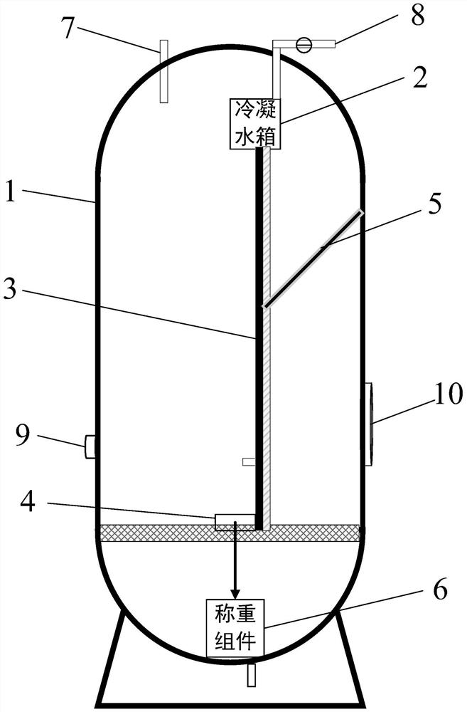
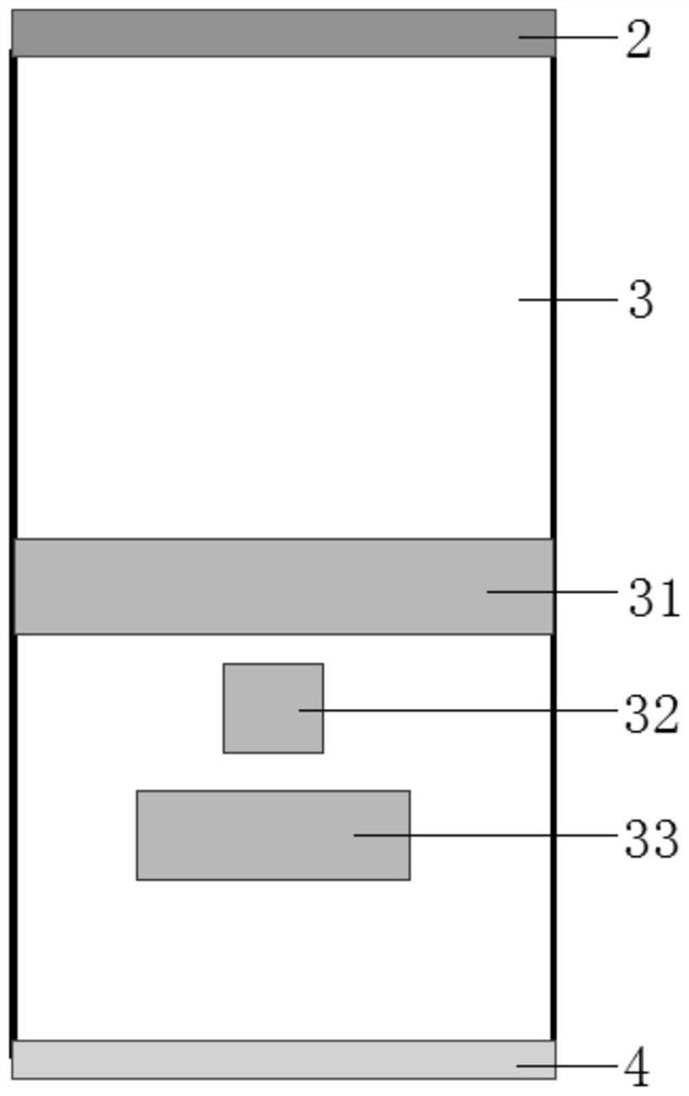
[0024] Such as figure 1 , figure 2 As shown, a test device for testing the recovery efficiency of condensate on the inner wall of the containment of a nuclear power plant, the device includes a tank body 1 for simulating the containment of a nuclear power plant, a condensate return assembly for simulating condensate return and collecting condensate water, and a condensate return assembly for collecting condensate The weighing component 6 for weighing the condensed water, the condensate return component and the weighing component 6 are all arranged inside the tank body 1, and the weighing component 6 is arranged at the condensate collecting end of the condensate return component. The weighing component 6 weighs the condensate recovered by the condensate return component, and calculates the condensate recovery efficiency by comparing with the inlet flow rate of the condensate return component.

[0025] The condensate return assembly includes a condensate water tank 2, a test m...


PUM


Abstract

The invention relates to a test device for testing the recovery efficiency of condensate on the inner wall surface of a nuclear power station containment vessel, which comprises a tank body (1) for simulating a nuclear power station containment vessel, a condensation reflux assembly for simulating condensation reflux and collecting condensate water, and a weighing assembly (6) for weighing the collected condensate water. The condensation reflux assembly and the weighing assembly (6) are both arranged in the tank body (1), and the weighing assembly (6) is arranged at the condensate water collecting end of the condensation reflux assembly. The weighing assembly (6) weighs the condensate recovered by the condensation reflux assembly, so that the condensate recovery efficiency is obtained. Compared with the prior art, the device can simulate the condensation reflux behavior of a nuclear power plant containment vessel inner wall surface condensate recovery system, and estimate the condensation reflux loss through weighing the recovered condensate water, thereby guiding the optimization design of the nuclear power plant containment vessel inner wall surface condensate recovery system.

Description

technical field [0001] The invention relates to the technical field of nuclear power plant optimization design, in particular to a test device for testing the recovery efficiency of condensate on the inner wall surface of the containment shell of a nuclear power plant. Background technique [0002] In the design of CAP1000 and CAP1400 of the third-generation independent advanced pressurized water reactor nuclear power plants, the passive residual heat removal (PRHR) system will play a vital role in the long-term cooling process under accident conditions. The in-containment refueling water tank (IRWST) in this system passes the water vapor generated by evaporation through the condensation return system to form condensate and finally returns to the IRWST during this process, which can ensure the water availability of the IRWST and thus support the long-term operation of the primary circuit. Cooling provides an important guarantee for the safety of the core. [0003] Prelimina...

Claims


Application Information

Patent Timeline
IPC IPC(8): G01N5/00G01K7/02G01F1/58G01L19/00
CPCG01N5/00G01K7/02G01F1/58G01L19/00Y02E30/30
Inventor 杨小杰胡珀潘新新王浩宇徐进胡真刘洁吴辉平李东祚刘冰刘佳
Owner SHANGHAI JIAO TONG UNIV
Learn More