Eureka AIR delivers breakthrough ideas for toughest innovation challenges, trusted by R&D personnel around the world.

Discrete array optimization algorithm for minimizing array element number of constraint directivity coefficient

A directivity and minimization technology, applied in the field of antennas, which can solve problems such as the reduction of directivity coefficients

Active Publication Date: 2021-06-25
UNIV OF ELECTRONICS SCI & TECH OF CHINA
View PDF4 Cites 10 Cited by
  • Summary
  • Abstract
  • Description
  • Claims
  • Application Information

AI Technical Summary

Problems solved by technology

However, these algorithms seldom consider the direct constraints on the directivity coefficient and the beam scanning range. Although the number of optimized sparse array elements can be significantly reduced, compared with the full array, its directivity coefficient is likely to There will be varying degrees of degradation, especially in scanning situations

Method used

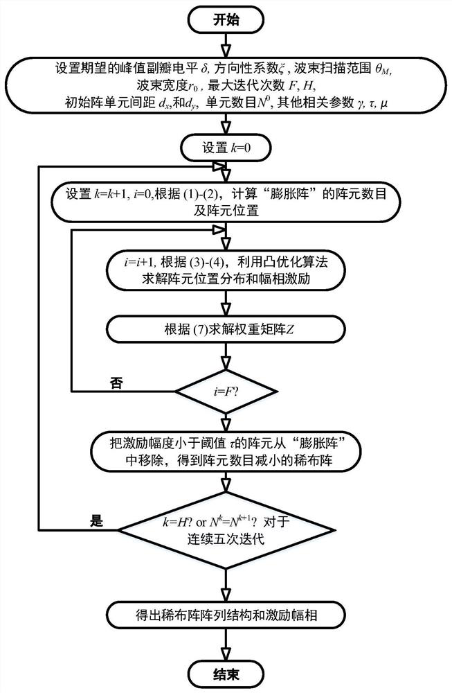

Image

  • Discrete array optimization algorithm for minimizing array element number of constraint directivity coefficient
  • Discrete array optimization algorithm for minimizing array element number of constraint directivity coefficient
  • Discrete array optimization algorithm for minimizing array element number of constraint directivity coefficient

Examples


Embodiment 1

[0033] Embodiment 1: The comprehensive maximum array diameter is L max =9.5λ sparse wiring array

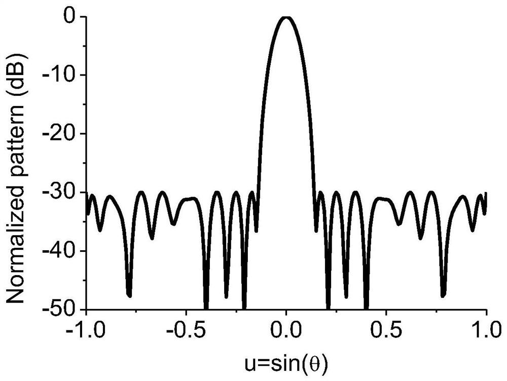
[0034] Consider a maximum array caliber L max =9.5λ sparse wiring array, the number of corresponding half-wavelength full array elements is equal to 20. In this implementation case, the desired beam scanning range is set to θ M =0 ° , the desired sidelobe level δ=-30dB, and the corresponding sidelobe area is |u|≥r 0 =0.14, the expected directivity coefficient is ξ=12.39dB. Other main parameters are as follows: τ=0.001, μ=0.001, F=15, H=30, d x =0.1λ,N 0 =96, γ=1 / 50.

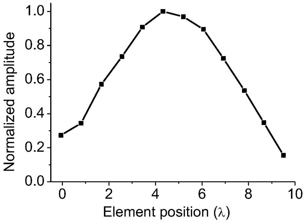
[0035] Utilize the optimization algorithm proposed in the present invention to optimize the position and excitation amplitude and phase of the sparsely distributed array elements, and the normalized pattern obtained by optimization is as follows figure 2 As shown, it can be seen that the peak sidelobe level was successfully suppressed below -30dB. The position distribution diagram of the optimized sparse a...

Embodiment 2

[0036] Embodiment 2: The comprehensive maximum array aperture is L max =7λ×7λ sparse planar array

[0037] Consider a maximum array caliber L max =7λ×7λ sparse plane array, the corresponding half-wavelength full array element number is equal to 15×15=225. In this implementation case, the desired beam scan range is θ M =57 ° , the desired peak sidelobe level δ=-25dB, the sidelobe area is {(u,v)|0.17^22 +v 2 ≤[1+sin(57 ° )] 2}, when the beam scans to (0, 57 ° ), the desired directivity coefficient is ξ=21.1dB. Other main parameters are as follows: τ=0.001, μ=0.001, F=15, H=30, d x = d y =0.5λ,N 0 =15×15=225, γ=1 / 20.

[0038] Also use the optimization algorithm proposed in the present invention to optimize the position of the sparse array elements and the excitation amplitude and phase, and the optimized obtained and The normalized direction map of the cut plane is as follows Figure 4 As shown, it can be seen that the peak sidelobe level is successfully suppresse...


PUM


Abstract

The invention discloses an array element number minimization sparse array optimization algorithm including directivity coefficient and beam scanning range constraint. According to the method, on the basis of a sparse array comprehensive framework, a dynamic array element position expansion and contraction mechanism is introduced, and a mathematical optimization model with the minimum array element number as a target function, the beam width, the peak side lobe level, the directivity coefficient and the beam scanning range as constraint conditions and the array element arrangement mode and amplitude-phase excitation as design parameters is established; and an iterative convex optimization algorithm is proposed to efficiently solve the mathematical optimization problem, and the required minimum array element number, array element position distribution and a corresponding amplitude-phase excitation vector are obtained. The maximum innovation of the method is that the established mathematical optimization problem considers the direct optimization of the directivity coefficient, has a feasible region range approaching the real sparse array element position, can consider the grating lobe problem occurring during sparse array scanning, and provides an efficient optimization algorithm for solving.

Description

technical field [0001] The invention belongs to the technical field of antennas, and relates to the joint optimization problem of sparse array arrangement and pattern synthesis, specifically refers to establishing As an optimization problem with flat constraints, the desired pattern can be achieved with the minimum number of array elements by optimizing the array element position and amplitude-phase excitation. The fast and high efficiency of this optimization method is mainly reflected in transforming the sparse array synthesis problem into an iterative convex optimization problem. Background technique [0002] The sparse array synthesis that minimizes the number of array elements that satisfies constraints such as given beamwidth, peak sidelobe level, and directivity coefficient has attracted more and more attention from researchers in phased array radar and wireless communication systems. Compared with the full half-wavelength uniform array, the sparse array can reduce t...

Claims


Application Information

Patent Timeline
Patent Type & Authority Applications(China)
IPC IPC(8): G06F30/20H01Q21/00G06F111/04G06F111/10
CPCG06F30/20G06F2111/04G06F2111/10H01Q21/00
Inventor 杨锋杨仕文陈科锦马彦锴黄明陈益凯屈世伟
Owner UNIV OF ELECTRONICS SCI & TECH OF CHINA
Why Eureka
Eureka Blog
Learn More