
Communication equipment and filter thereof

A filter and filter cavity technology, which is applied in the field of communication, can solve the problems of large size and high cost of the filter, and achieve the effects of zero-point suppression, volume reduction, and cost reduction

Inactive Publication Date: 2021-06-25
ANHUI TATFOOK TECH CO LTD
View PDF5 Cites 0 Cited by
  • Summary
  • Abstract
  • Description
  • Claims
  • Application Information

AI Technical Summary

Problems solved by technology

[0003] The inventors of the present application found in long-term research and development work that the filter cavities of the current filter are arranged on the same side, and the volume of the filter is relatively large and the cost is relatively high

Method used


Image

  • Communication equipment and filter thereof
  • Communication equipment and filter thereof
  • Communication equipment and filter thereof

Examples


Embodiment Construction

[0031] In order to enable those skilled in the art to better understand the technical solution of the present application, the communication device and the filter provided by the invention will be further described in detail below in conjunction with the drawings and specific implementation methods.

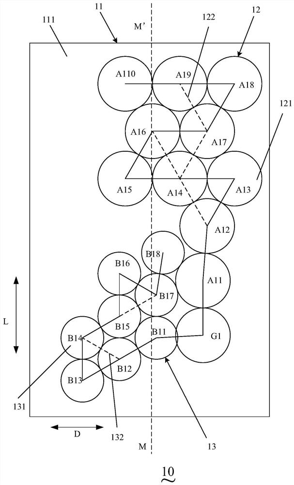
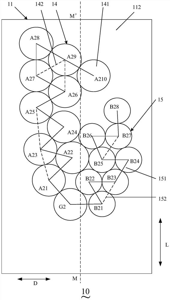
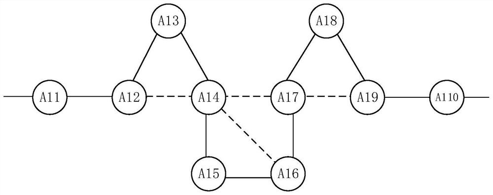
[0032] This application provides a filter, see Figure 1 to Figure 6 , figure 1 is a schematic structural view of the first surface of an embodiment of the filter of the present application, figure 2 is a schematic structural diagram of the second surface of an embodiment of the filter of the present application, image 3 is a schematic diagram of the topological structure of the first filtering branch in the filter of the present application, Figure 4 is a schematic diagram of the topology of the second filtering branch in the filter of the present application, Figure 5 is a schematic diagram of the topology of the third filtering branch in the filter of the present applic...


PUM


Abstract

The invention discloses communication equipment and a filter thereof. The filter comprises: a shell provided with a first direction and a second direction which are perpendicular to each other and comprising a first surface and a second surface which are arranged oppositely; a first common cavity arranged on the first surface of the shell; a first filtering branch coupled with the first common cavity and comprising ten filtering cavities which are coupled in sequence, wherein four cross coupling zero points are formed; a second filtering branch coupled with the first common cavity and comprising eight filtering cavities which are coupled in sequence, wherein two cross coupling zero points are formed; a second common cavity arranged on the second surface of the shell; a third filtering branch coupled with the second common cavity and comprising ten filtering cavities which are coupled in sequence, wherein four cross coupling zero points are formed; and a fourth filtering branch coupled with the second common cavity and comprising eight filtering cavities which are coupled in sequence, wherein two cross coupling zero points are formed. According to the invention, the four filtering branches are respectively arranged on the front and back surfaces of the shell, so that the volume of the filtering cavity can be reduced, and the cost is reduced.

Description

technical field [0001] The present application relates to the technical field of communication, in particular to a communication device and a filter thereof. Background technique [0002] In the mobile communication system, the required signal is modulated to form a modulated signal, and carried on the high-frequency carrier signal, transmitted to the air through the transmitting antenna, and the signal in the air is received through the receiving antenna. Among the signals received by the receiving antenna, not only Include the desired signal, but also include other frequency harmonics, noise signals. For the signal received by the receiving antenna, it is necessary to use a filter to filter out unnecessary harmonics and noise signals. Therefore, the designed filter must precisely control its bandwidth. [0003] The inventors of the present application have discovered during long-term research and development work that the filter cavities of the current filter are arrange...

Claims


Application Information

Patent Timeline
Patent Type & Authority Applications(China)
IPC IPC(8): H01P1/208H01P1/209
CPCH01P1/208H01P1/209
Inventor 张海峰周峰贺从虎赵志敏
Owner ANHUI TATFOOK TECH CO LTD
Learn More