Multi-mode excitation structure based on compact resonator
A resonant cavity and multi-mode technology, applied in resonators, phase influence characteristic measurement, instruments, etc., can solve problems such as complex MIM waveguide structures, achieve strong field confinement capabilities, and simplify structures
- Summary
- Abstract
- Description
- Claims
- Application Information
AI Technical Summary
Problems solved by technology
Method used
Image
Examples
Embodiment 1
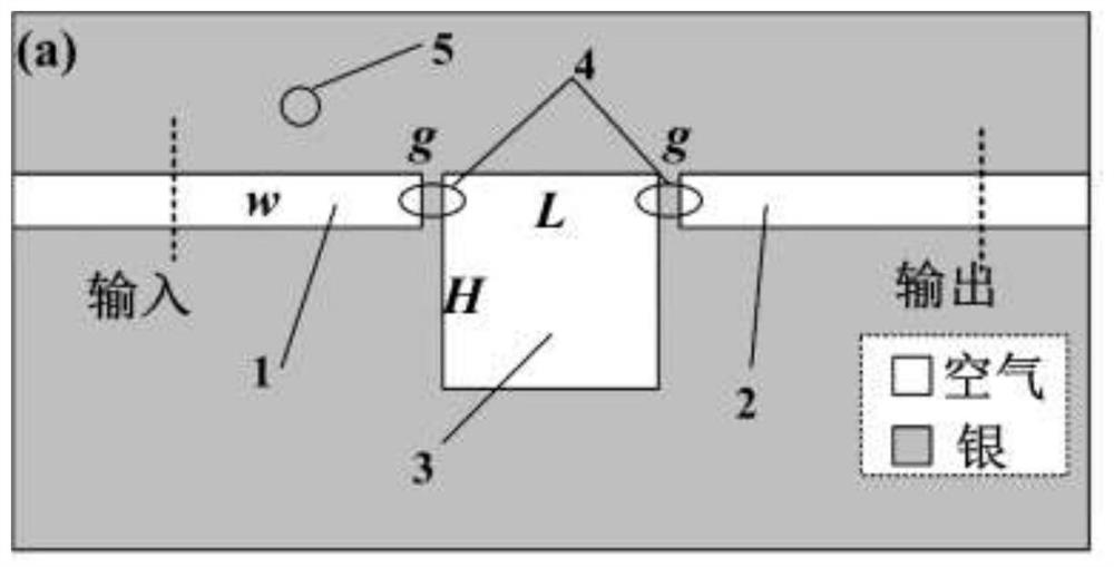
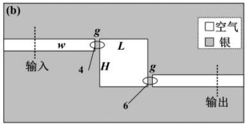
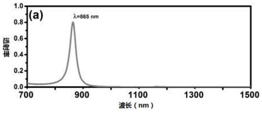
[0040]As shown in Figure 1, both the input channel and the output channel are coupled with the upper end of the resonant cavity. In this structure, the refractive index of the filling material in the resonant cavity is n=1.00. Figure 2a For its transmission spectrum, there is only one transmission peak at λ=865nm. Figure 2c is the distribution diagram of the magnetic field mode at the peak position, from which it can be seen that this is a typical antisymmetric mode. When the resonant cavity and the output channel are coupled at the bottom, the structure is as follows Figure 1b , whose transmission spectrum is as Figure 2b . It can be seen by comparison that, in addition to the transmission peak at the original position, λ=865nm, there is another transmission peak at λ=1162nm. Figure 2d Its magnetic field mode distribution diagram shows that the energy of SPPs is concentrated in the opposite corner of the resonator, which we call the corner mode. The above two struct...
Embodiment 2
[0043] Such as image 3 As shown, at this time, the input channel is still coupled with the resonant cavity at the upper end, while the output channel is coupled with the resonant cavity at the bottom end. Figure 4a Given that L=H changes at the same time, image 3 The variation of the transmission spectrum of the structure shown, Figure 4a A plot of each mode versus L=H is given in the inset. It can be seen that the new structure system co-excites four different cavity modes, and each cavity mode changes in direct proportion to L=H, which provides a reference for realizing specific wavelength selection. Figure 4b -e respectively shows the distribution of the magnetic field modes corresponding to each mode, at this time L=H=500nm. The four modes correspond to each other: Mode A, λ=865nm, is an anti-symmetric mode, which maintains the law of the previous structure; Mode B, λ=1132nm, is a left-right symmetric mode; valley mode, λ=1152nm, is an angular mode, which is the sa...
PUM
 Abstract
Description
Claims
Application Information
 - R&D
- Intellectual Property
- Life Sciences
- Materials
- Tech Scout
- Unparalleled Data Quality
- Higher Quality Content
- 60% Fewer Hallucinations
Browse by: Latest US Patents, China's latest patents, Technical Efficacy Thesaurus, Application Domain, Technology Topic, Popular Technical Reports.
© 2025 PatSnap. All rights reserved.Legal|Privacy policy|Modern Slavery Act Transparency Statement|Sitemap|About US| Contact US: help@patsnap.com


