Clock synchronization method and device and video processing equipment
A clock synchronization and clock frequency technology, applied in the direction of synchronization devices, digital transmission systems, electrical components, etc., can solve the problem that the phase-locked loop chip is expensive, cannot flexibly lock the input source synchronization reference signal, and is not suitable for cost-sensitive products Problems such as batch use, to achieve the effect of facilitating batch use and reducing costs
- Summary
- Abstract
- Description
- Claims
- Application Information
AI Technical Summary
Problems solved by technology
Method used
Image
Examples
no. 1 example
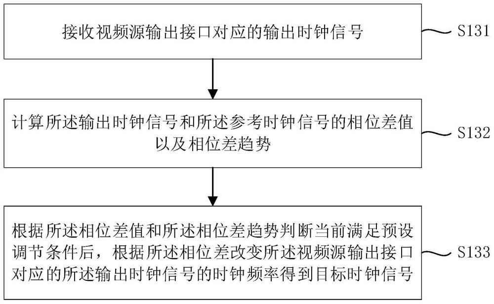
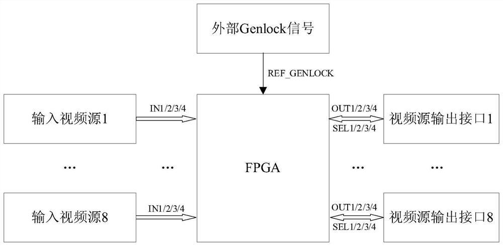
[0040] see figure 1 and figure 2 , the first embodiment of the present invention proposes a clock synchronization method. Such as figure 1 and figure 2 As shown, the clock synchronization method includes, for example, steps S11 to S13 and steps S131 to S133.
[0041] Step S11: receiving a reference clock signal;
[0042] Step S13: judging the type of the reference clock signal, and in the case of judging that the reference clock signal is an external clock signal, proceed to step S131 to step S133;
[0043] Step S131: receiving an output clock signal corresponding to the video source output interface;
[0044] Step S132: Calculate the phase difference value and phase difference trend between the output clock signal and the reference clock signal;
[0045] Step S133: After judging according to the phase difference value and the phase difference trend that the preset adjustment condition is satisfied, change the clock frequency of the output clock signal corresponding to...
no. 2 example
[0062] see Figure 5 , the second embodiment of the present invention provides a clock synchronization device. Such as Figure 5 As shown, the clock synchronization device 20 includes, for example, a signal receiving module 21 and a judgment processing module 23 .
[0063] Wherein, the signal receiving module 21 is used for receiving a reference clock signal. The judging processing module 23 is used to judge the type of the reference clock signal, and in the case of judging that the reference clock signal is an external clock signal, perform the following steps: receive the output clock signal corresponding to the video source output interface; calculate the output The phase difference value and the phase difference trend of the clock signal and the reference clock signal; and after judging according to the phase difference value and the phase difference trend that the preset adjustment condition is satisfied, changing the output of the video source according to the phase di...
no. 3 example
[0067] join Figure 6 , the third embodiment of the present invention provides a video processing device. Such as Figure 6 As shown, the video processing device 30 includes, for example: a microcontroller 31 , a clock generator 32 , a programmable logic device 33 and a video source output interface 34 .
[0068] Wherein, the clock generator 32 is connected to the microcontroller 31, the programmable logic device 33 is connected to the microcontroller 31, and the video source output interface 34 is connected to the clock generator 32 and the programmable logic device 33, wherein the programmable logic device 33, for example, executes as A clock synchronization method described in an embodiment. For the description of the clock synchronization method, reference may be made to the first embodiment, and details are not repeated here for the sake of brevity.
[0069] Further, the microcontroller 31 is used to send the mode switching instruction to the programmable logic device ...
PUM
 Abstract
Description
Claims
Application Information
 - R&D
- Intellectual Property
- Life Sciences
- Materials
- Tech Scout
- Unparalleled Data Quality
- Higher Quality Content
- 60% Fewer Hallucinations
Browse by: Latest US Patents, China's latest patents, Technical Efficacy Thesaurus, Application Domain, Technology Topic, Popular Technical Reports.
© 2025 PatSnap. All rights reserved.Legal|Privacy policy|Modern Slavery Act Transparency Statement|Sitemap|About US| Contact US: help@patsnap.com


