
Clamping device for precision machining of gears of various sizes

A technology of precision machining and clamping device, which is applied in the field of gear machining and can solve the problems of single function and inability to perform multi-directional machining.

Inactive Publication Date: 2021-06-29
长沙协创智赢技术服务有限公司
View PDF0 Cites 0 Cited by
  • Summary
  • Abstract
  • Description
  • Claims
  • Application Information

AI Technical Summary

Problems solved by technology

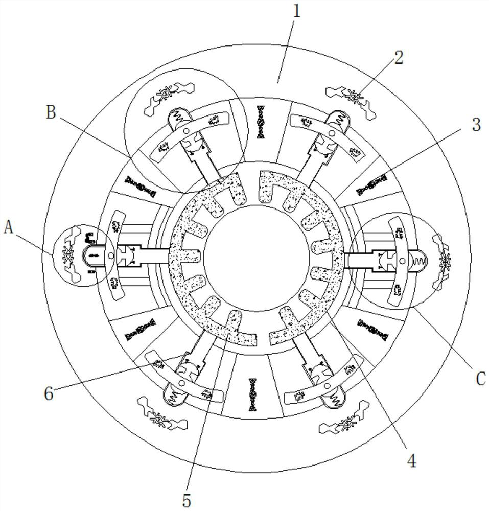
[0006] Aiming at the deficiencies of the prior art, the present invention provides a clamping device for precision machining of gears of various sizes, which has the advantage of clamping and fixing gears of different sizes, and solves the problem of the single function of traditional fixings and the inability to perform multi-directional processing The problem

Method used


Image

  • Clamping device for precision machining of gears of various sizes
  • Clamping device for precision machining of gears of various sizes
  • Clamping device for precision machining of gears of various sizes

Examples

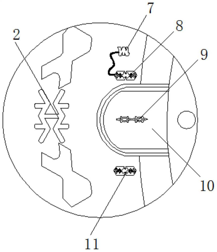
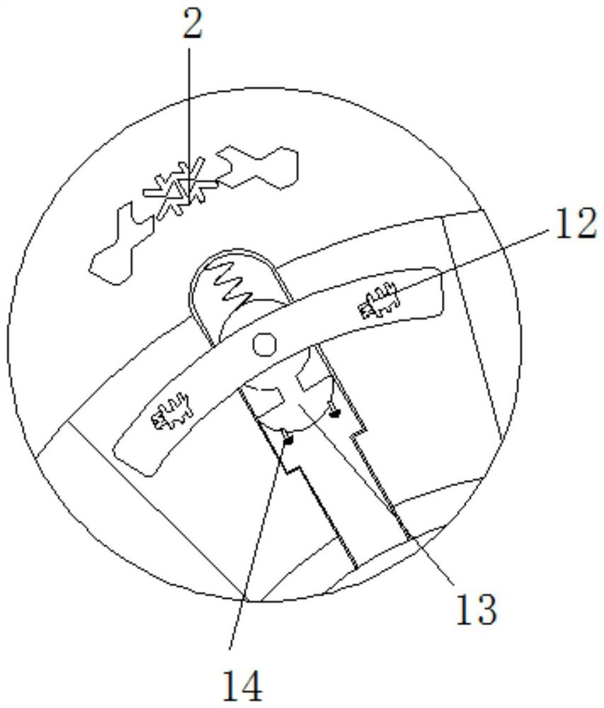

Embodiment Construction

[0025] The following will clearly and completely describe the technical solutions in the embodiments of the present invention with reference to the accompanying drawings in the embodiments of the present invention. Obviously, the described embodiments are only some, not all, embodiments of the present invention. Based on the embodiments of the present invention, all other embodiments obtained by persons of ordinary skill in the art without making creative efforts belong to the protection scope of the present invention.

[0026] see Figure 1-4 , a clamping device for precision machining of gears of various sizes, including a base 1, and a movable groove matching the deformation sleeve 4 is provided in the middle of the base 1. When the gear is put into the movable groove, the deformation sleeve 4 is squeezed along the The movable groove shrinks or expands, and the inner wall of the middle part of the base 1 is fixedly connected with the electromagnet 2. The size of the electro...


PUM


Abstract

The invention relates to the technical field of gear machining, and discloses a clamping device for precision machining of gears of various sizes. The clamping device comprises a base, an electromagnet is fixedly connected to the inner wall of the middle of the base, a non-magnetic plate is fixedly connected to the inner wall of the middle of the base, a deformation sleeve is movably connected to the inner wall of the middle of the base, electrorheological fluid is movably connected to the inner wall of the deformation sleeve, and the middle inner wall of the base is fixedly connected with an extrusion column. According to the clamping device for precise machining of the gears of the various sizes, an electromagnet drives a magnetic block to operate, the magnetic block drives a trigger block to move, then a dielectric plate is matched with a positive plate and a negative plate for use, therefore the effect of controlling power-on and power-off of a conductive column is achieved, the electromagnet generates a magnetic field, at the moment, the magnetic block is subjected to inward repulsive force, a piston and the trigger block move, the trigger block drives the dielectric plate to generate relative displacement which is gradually increased, at the moment, the relative area of the positive plate and the negative plate is changed, the area is gradually increased, and the working voltage of a piezoresistor is reached, so that the conductive column is powered on.

Description

technical field [0001] The invention relates to the technical field of gear processing, in particular to a clamping device for precision machining of gears of various sizes. Background technique [0002] Gears are the core transmission components in mechanical motion. The quality of their processing will have a direct impact on the performance and reliability of the mechanical assembly and even the entire device. Most of the gears are produced by cutting and grinding by machine tools. , when it is processed, it is usually fixed on the base of the machine tool with a fixture, and then processed by a machine tool drill. [0003] Most of the existing fixing parts are simple in structure and poor in stability, and are easy to loosen during processing, which will affect the machining accuracy and reduce the quality of the finished gear, and many fixing parts only have the type of horizontal or vertical clamping. function, the multi-directional processing of gears cannot be reali...

Claims


Application Information

Patent Timeline
Patent Type & Authority Applications(China)
IPC IPC(8): B23F23/06B23Q3/08
CPCB23F23/06B23Q3/086
Inventor 韦丽红程晓安吕文光
Owner 长沙协创智赢技术服务有限公司
Learn More