Tool for disassembling bearing outer ring of printing rubber roller

A technology of bearing outer ring and printing rubber roller, applied in the field of printing machinery, can solve the problems of rubber roller damage, time-consuming, wear of support bearing, etc.

Inactive Publication Date: 2021-06-29
郑强
View PDF0 Cites 0 Cited by
  • Summary
  • Abstract
  • Description
  • Claims
  • Application Information

AI Technical Summary

Problems solved by technology

At the same time, the supporting bearing of the rubber roller body will also be worn due to high-speed operation, the bearing cage is broken, the inner ring of the bearing comes out, and the outer ring of the bearing is still set in the bearing hole of the rubber roller body
The outer ring of this kind of bearing is difficult to remove, which will cause the rubber roller to be unusable
The usual method is to weld a rod on the outer ring of the bearing, and continuously tap the welded rod to drive the outer ring of the bearing to vibrate, thereby driving the outer ring of the bearing to slowly come out of the rubber roller body. Although this method is commonly used, it takes a long time , and because the high temperature and spattered welding slag generated during welding are easy to damage the rubber layer of the rubber roller, resulting in damage to the rubber roller

Method used


Image

  • Tool for disassembling bearing outer ring of printing rubber roller
  • Tool for disassembling bearing outer ring of printing rubber roller
  • Tool for disassembling bearing outer ring of printing rubber roller

Examples


Embodiment 1

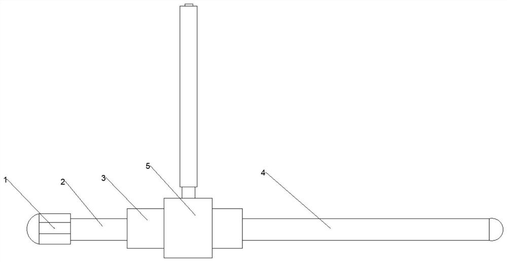
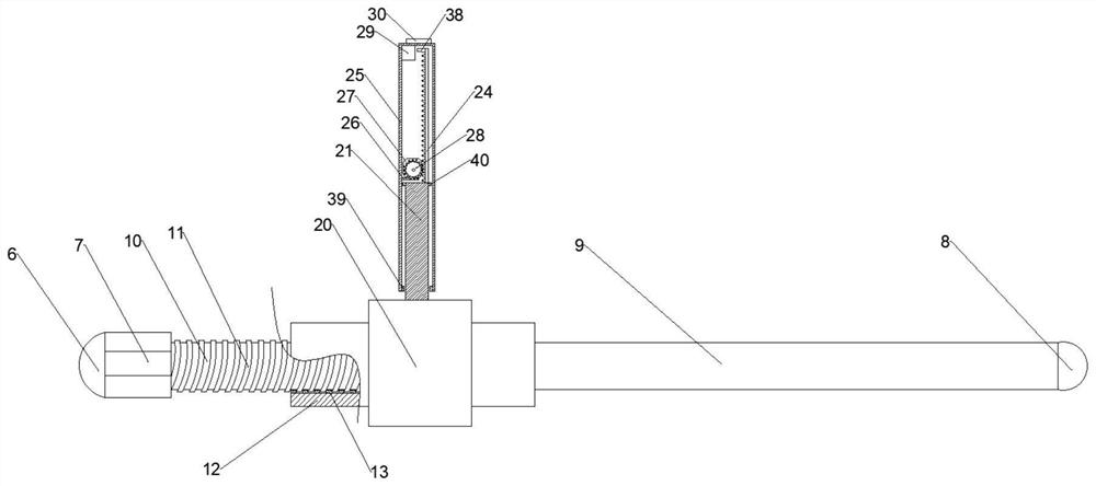
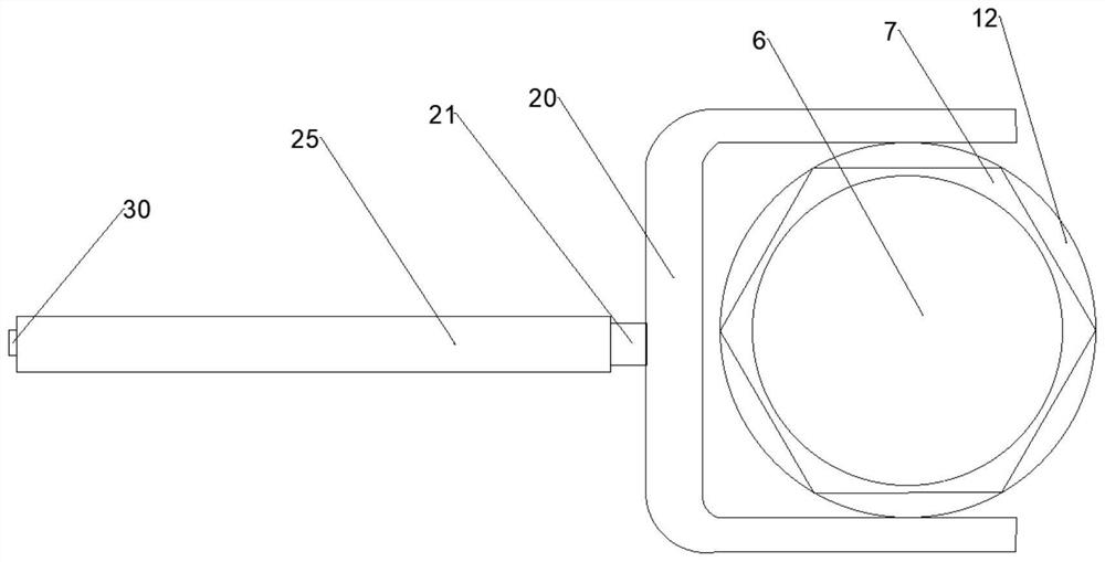
[0032] Please refer to Figure 1-3 , figure 1 It is a front view of a tool for disassembling the outer ring of printing rubber roller bearing according to the embodiment of the present invention; figure 2 It is a partial sectional view of a tool for removing the outer ring of a printing rubber roller bearing according to an embodiment of the present invention; image 3 It is a side view of a tool for removing the outer ring of a printing roller bearing according to an embodiment of the present invention.

[0033] This embodiment provides a tool for dismounting the outer ring of the printing rubber roller bearing, including a first ejector rod 1 in contact with the outer ring of the bearing, a connector 2 connected to the first ejector rod 1 , and a telescopic The connected sleeve joint 3, the second ejector rod 4 connected to the sleeve joint 3 and in contact with the outer ring of the bearing, and the electric punch 5 connected to the sleeve joint 3, wherein the diameter o...

Embodiment 2

[0036] Please refer to Figure 1-3 , figure 1 It is a front view of a tool for disassembling the outer ring of printing rubber roller bearing according to the embodiment of the present invention; figure 2 It is a partial sectional view of a tool for removing the outer ring of a printing rubber roller bearing according to an embodiment of the present invention; image 3 It is a side view of a tool for removing the outer ring of a printing roller bearing according to an embodiment of the present invention.

[0037] This embodiment improves a tool for removing the outer ring of the printing rubber roller bearing, which is basically the same as the tool for removing the outer ring of the printing rubber roller bearing in Embodiment 1. The difference between the two is mainly: the second ejector rod 4 includes a second contact section 8 that is in contact with the outer ring of the bearing and has an arc-shaped surface, and a second push section 9 that is connected to the second...

Embodiment 3

[0040] Please refer to Figure 1-3 , figure 1 It is a front view of a tool for disassembling the outer ring of printing rubber roller bearing according to the embodiment of the present invention; figure 2 It is a partial sectional view of a tool for removing the outer ring of a printing rubber roller bearing according to an embodiment of the present invention; image 3 It is a side view of a tool for removing the outer ring of a printing roller bearing according to an embodiment of the present invention.

[0041] This embodiment improves a tool for removing the outer ring of the printing rubber roller bearing, which is basically the same as the tool for removing the outer ring of the printing rubber roller bearing in Embodiment 1. The difference between the two is mainly: the first ejector rod 1 includes a first contact segment 6 that is in contact with the outer ring of the bearing and has an arc-shaped surface, and a first push segment 7 connected to the first contact seg...


PUM


Abstract

The invention provides a tool for disassembling a bearing outer ring of a printing rubber roller, and relates to the technical field of printing machinery. The tool for disassembling a bearing outer ring of a printing rubber roller comprises a first ejection rod making contact with the bearing outer ring, a connector fixedly connected with the first ejection rod, a sleeving connection head connected with the connector in a telescopic mode, a second ejection rod fixedly connected with the sleeving connection head and making contact with the bearing outer ring, and an electric punching rod perpendicularly connected with the sleeving connection head. The diameter of the first ejection rod is larger than that of the connector. The bearing outer ring can be driven to be separated from the rubber roller, a rubber roller barrel and a rubber layer on the surface can be protected as much as possible, and the aim of not damaging the rubber layer of the rubber roller is achieved.

Description

technical field [0001] The invention relates to the technical field of printing machinery, in particular to a tool for disassembling the outer ring of a printing rubber roller bearing. Background technique [0002] In the lithographic printing machine industry, the printing rubber roller of the printing unit is defined as a general wearing part. During the printing process, the rubber layer on the surface of the printing rubber roller is easy to wear and tear. At the same time, the supporting bearing of the rubber roller body will also be worn due to high-speed operation, the bearing cage will break, the inner ring of the bearing will come out, and the outer ring of the bearing will still be sleeved in the bearing hole of the rubber roller body. The outer ring of this kind of bearing is difficult to remove, which will make the rubber roller unusable. The usual method is to weld a rod on the outer ring of the bearing, and continuously tap the welded rod to drive the outer ri...

Claims


Application Information

Patent Timeline
Patent Type & Authority Applications(China)
IPC IPC(8): B25B27/02
CPCB25B27/023
Inventor 郑强
Owner 郑强
Why Eureka
Try Eureka