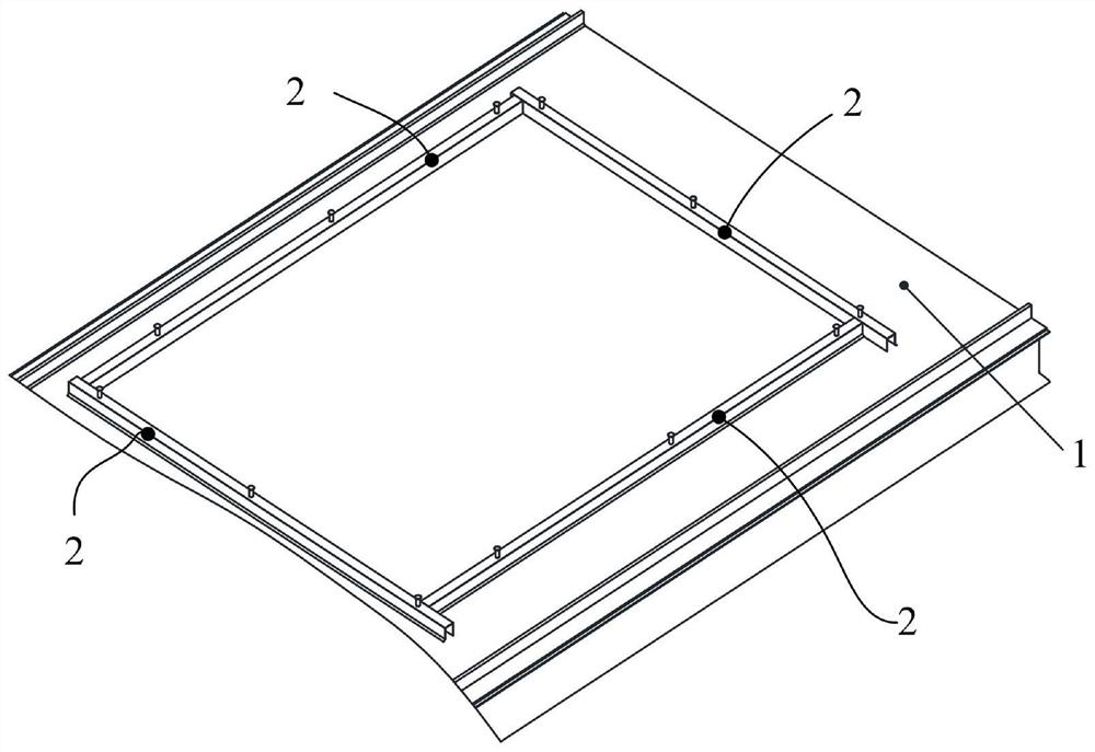
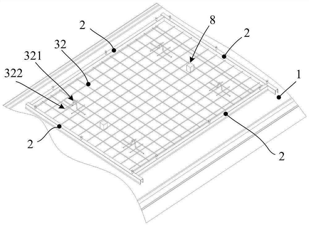
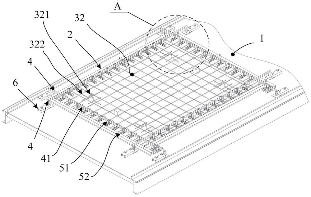
Production device and production method of grooved laminated slab without bars on periphery

A production device and production method technology, applied to mold fixing devices, ceramic molding machines, molds, etc., can solve problems such as increased workload, inconvenient lifting and transportation, and physical injuries of operators, so as to improve work efficiency and high production efficiency , Improve the effect of construction work efficiency

Inactive Publication Date: 2021-06-29
CHINA CONSTR SCI & TECH CO LTD +1
View PDF5 Cites 5 Cited by
  • Summary
  • Abstract
  • Description
  • Claims
  • Application Information

AI Technical Summary

Problems solved by technology

In addition, the prefabricated slabs of the prior art need to place steel mesh before pouring. In order to facilitate the subsequent connection with the steel bars of the building, the plane size of the steel mesh is usually set to be larger than the plane size of the prefabricated slab, so the prefabricated slab after pouring is at the edge position Short steel bars reserved for convex
[0004] Although the short steel bars here can be easily welded and connected to the structure during later installation, the protruding short steel bars cause great inconvenience in lifting and transportation, and are likely to cause bodily injury to operators
More importantly, to connect two prefabricated slabs, it is necessary to open corresponding installation grooves at the relative positions and weld the relative steel bars together, which not only increases the workload but also requires the operator to have relatively skilled operating skills

Method used


Image

  • Production device and production method of grooved laminated slab without bars on periphery
  • Production device and production method of grooved laminated slab without bars on periphery
  • Production device and production method of grooved laminated slab without bars on periphery

Examples


Embodiment Construction

[0055] The technical solutions in the embodiments of the present invention will be clearly and completely described below with reference to the accompanying drawings in the embodiments of the present invention. Obviously, the described embodiments are only a part of the embodiments of the present invention, not all of the embodiments. Based on the embodiments of the present invention, all other embodiments obtained by those of ordinary skill in the art without creative efforts shall fall within the protection scope of the present invention.

[0056] It should be noted that if there are directional indications (such as up, down, left, right, front, back, etc.) involved in the embodiments of the present invention, the directional indications are only used to explain a certain posture (as shown in the accompanying drawings). If the specific posture changes, the directional indication also changes accordingly.

[0057] In addition, if there are descriptions involving "first", "sec...


PUM


Abstract

The invention discloses a production device and a production method of a grooved laminated slab without bars on the periphery. In the production process of prefabricated slabs, an automated production line is adopted. Before the prefabricated slabs are poured, a plurality of equidistant groove assemblies are arranged and the groove assemblies are inserted into the surface layers of the prefabricated slabs. After the prefabricated slabs are poured and fully solidified, groove holes capable of containing middle connecting steel bars are formed, and then the middle connecting steel bars are mounted in a matched mode, so that reliable connection of every two adjacent prefabricated slabs and adaptive matched connection of a subsequently poured laminated slab and a building body are achieved. The prefabricated slabs are produced through the automated production line, groove blocks are placed through a mechanical arm, wedge-shaped ribbed groove blocks are formed through synthetic resin, and the connecting bars are sequentially placed in the groove holes during field mounting, so that the crack resistance and the meshing effect of the concrete laminated slab are enhanced, the production efficiency is improved, and the total construction cost is reduced. Reliable supporting and pouring safety are ensured through a supporting mechanism.

Description

technical field [0001] The invention relates to the technical field of prefabricated panels for structures, in particular to a production device and a production method for a laminated board with no ribs and grooves around it. Background technique [0002] In the construction industry, in order to speed up the progress of the project and ensure the quality of the building, part of the structure of the construction project is usually produced in the factory by means of an assembly line, which can not only speed up the progress and ensure the quality, but also reduce the production cost. [0003] Among them, in the production of prefabricated parts, since the prefabricated board is usually a flat board structure, it only needs to be produced in a tiled manner. In addition, the prefabricated panels of the prior art need to be placed with reinforcing meshes before pouring. In order to facilitate the subsequent connection with the reinforcing bars of the building, the plane size ...

Claims


Application Information

Patent Timeline
Patent Type & Authority Applications(China)
IPC IPC(8): B28B1/04B28B1/087B28B7/00B28B7/22B28B11/24B28B23/02
CPCB28B7/002B28B7/22B28B23/02B28B1/087B28B1/045B28B11/245
Inventor 钟志强黄朝俊刘昌波张卫曾欠谱罗雨
Owner CHINA CONSTR SCI & TECH CO LTD
Why Eureka
Try Eureka