Injection mold with cooling function

An injection mold and functional technology, applied in the field of injection molds with cooling function, can solve the problems of affecting the yield of the mold, the mold release cannot be carried out smoothly, and the temperature cannot be effectively isolated, so as to reduce the difficulty and improve the stability. The effect of sealing and improving yield

Inactive Publication Date: 2021-06-29
广东华粤售电有限公司
View PDF0 Cites 0 Cited by
  • Summary
  • Abstract
  • Description
  • Claims
  • Application Information

AI Technical Summary

Problems solved by technology

[0004] Since the connection of the injection port of the mold cannot effectively insulate the temperature, if the molded product is cooled before the mold is demolded in a high temperature environment, the high temperature outside the mold will easily prevent the top processed product from being completely cooled, resulting in Subsequent demoulding of the mold cannot be carried out smoothly, which affects the yield of mold processing

Method used


Image

  • Injection mold with cooling function
  • Injection mold with cooling function
  • Injection mold with cooling function

Examples


Embodiment 1

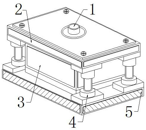
[0029] as attached figure 1 to attach Figure 5 Shown:

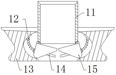
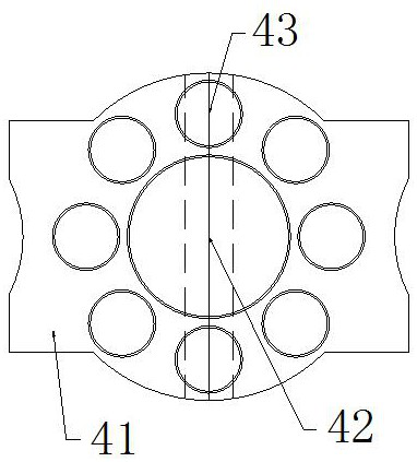
[0030] The invention provides an injection mold with a cooling function, the structure of which includes an injection port 1, an upper mold base 2, a cooling plate 3, a guide post 4, and a lower mold base 5, and the injection port 1 is installed in the middle of the upper mold base 2 , the cooling plate 3 is installed between the upper mold base 2 and the lower mold base 5, the guide post 4 is embedded between the upper mold base 2 and the lower mold base 5, and the injection port 1 is provided with a guide wall 11 , push bar 12, base 13, sealing layer 14, opening and closing plate 15, described guide wall 11 is installed in the middle of injection molding port 1, and described pushing bar 12 is embedded between base 13 and opening and closing plate 15, and described sealing layer 14 is embedded and connected with the opening and closing block 15, and the opening and closing plate 15 is hinged on both sides of the bott...

Embodiment 2

[0038] as attached Figure 7 to attach Figure 8 Shown:

[0039] The present invention provides an injection mold with a cooling function. The opening and closing plate 15 is provided with a hinge block 51, a rubber block 52, a gravity ball 53, and a weight plate 54. The hinge block 51 is embedded and fixed on the top of the left end of the opening and closing block 15. The rubber block 52 is installed on the right end of the opening and closing plate 15, the gravity ball 53 is matched with the internal clearance of the opening and closing plate 15, the weight plate 54 is embedded and connected with the opening and closing plate 15, and the rubber block 52 can be pressed after being squeezed. It fits tightly therebetween, and the gravity ball 53 faces down all the time due to gravity, and can roll inside it with the swing of the opening and closing plate 15. When the opening and closing plate 15 is opened, the gravity ball 53 makes its fixed position not Easy to close, if th...


PUM


Abstract

The invention provides a injection mold with a cooling function. The injection mold with the cooling function structurally comprises an injection molding opening, an upper mold base, a cooling plate, a guide column and a lower mold base, the injection molding opening is formed in the middle of the upper mold base, the cooling plate is installed between the upper mold base and the lower mold base, and the guide column is fixedly embedded between the upper mold base and the lower mold base. According to the injection mold with the cooling function, during cooling before demolding, generated cold air and hot air flow in the mold are opposite to each other, a bag layer in a sealing layer is jacked upwards, so that the joint of the injection molding opening can be effectively insulated from the temperature, and the problem that subsequent demolding of the mold cannot be smoothly carried out due to the fact that a processed product at the top end of the mold cannot be completely cooled is avoided; and then the mold processing yield is improved, the attaching degree between two opening and closing plates is stabilized through a gravity ball and a weight increasing plate, suction cups of rubber blocks are mutually adsorbed, so that the sealing stability and sealing performance of the outer layer of the injection molding opening are improved, the high temperature outside the mold cannot directly influence the internal cooling, and the subsequent demolding difficulty is reduced.

Description

technical field [0001] The invention belongs to the field of injection cooling equipment, and more specifically relates to an injection mold with a cooling function. Background technique [0002] The injection mold with cooling function is to quickly cool the injection mold and its internal processed products through the equipped cooling system, thereby speeding up the molding of processed products, and is usually used for the processing of plastic materials such as plastic parts. [0003] Based on the above description, the inventors found that the existing injection mold with cooling function mainly has the following deficiencies, such as: [0004] Since the connection of the injection port of the mold cannot effectively insulate the temperature, if the molded product is cooled before the mold is demolded in a high temperature environment, the high temperature outside the mold will easily prevent the top processed product from being completely cooled, resulting in The sub...

Claims


Application Information

Patent Timeline
Patent Type & Authority Applications(China)
IPC IPC(8): B29C45/26B29C45/73
CPCB29C45/2602B29C45/2608B29C45/7337
Inventor 范福明
Owner 广东华粤售电有限公司
Why Eureka
Try Eureka