Continuous conveying system and method for solid-liquid mixed materials

A solid-liquid mixing and conveying system technology, applied in conveyors, conveying bulk materials, transportation and packaging, etc., can solve the problems of large conveying pulses, gear wear, and reduce the service life of gear pumps, and achieve small pulses and long service life. , The effect of high conveying efficiency

Inactive Publication Date: 2021-06-29
杭州精进科技有限公司
View PDF5 Cites 0 Cited by
  • Summary
  • Abstract
  • Description
  • Claims
  • Application Information

AI Technical Summary

Problems solved by technology

The plunger pump has the advantages of equal pressure conveying and isolated conveying between the pump and the material. However, because the plunger pump has a return stroke, it cannot realize continuous conveying of the material, and intermittent material conveying will result in large conveying pulses and poor material conveying effect. it is good
The gear pump can realize the continuous conveying of the material and the pulse is small, but the gear pump cannot realize the isolation from the material; especially when the material is a solid-liquid mixed material, the solid particles in the mixed material will seriously wear the gear in the gear pump, seriously deteriorating the gear. pump life

Method used


Image

  • Continuous conveying system and method for solid-liquid mixed materials
  • Continuous conveying system and method for solid-liquid mixed materials
  • Continuous conveying system and method for solid-liquid mixed materials

Examples


Embodiment 1

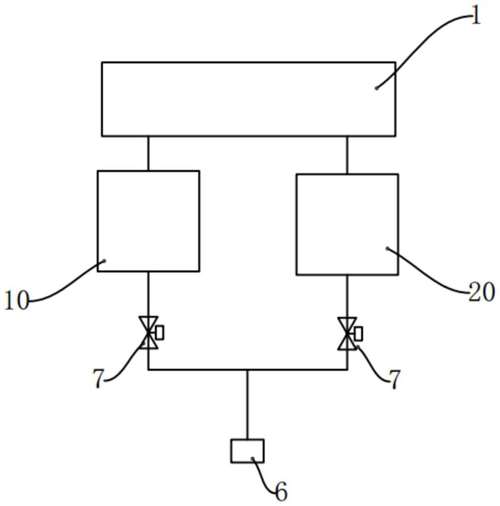
[0035] see figure 1 , which is a schematic block diagram of Embodiment 1 of the continuous delivery system for solid-liquid mixture materials of the present invention. An embodiment of the present invention discloses a continuous conveying system for solid-liquid mixture materials, including a discharge main path 6, a first conveying branch 10 and a second conveying branch 20, wherein the first conveying branch 10 and the second conveying branch The two conveying branches 20 are independent of each other and both discharge and feed according to the set cycle, and when the first conveying branch 10 is discharging, the second conveying branch 20 is fed from the storage container 1, and the second When the conveying branch 20 is discharging, the first conveying branch 10 is fed from the material container 1; Road 6 communicates, and the first conveying branch 10 and the second conveying branch 20 are communicated with the discharge main road 6 during their respective discharge p...

Embodiment 2

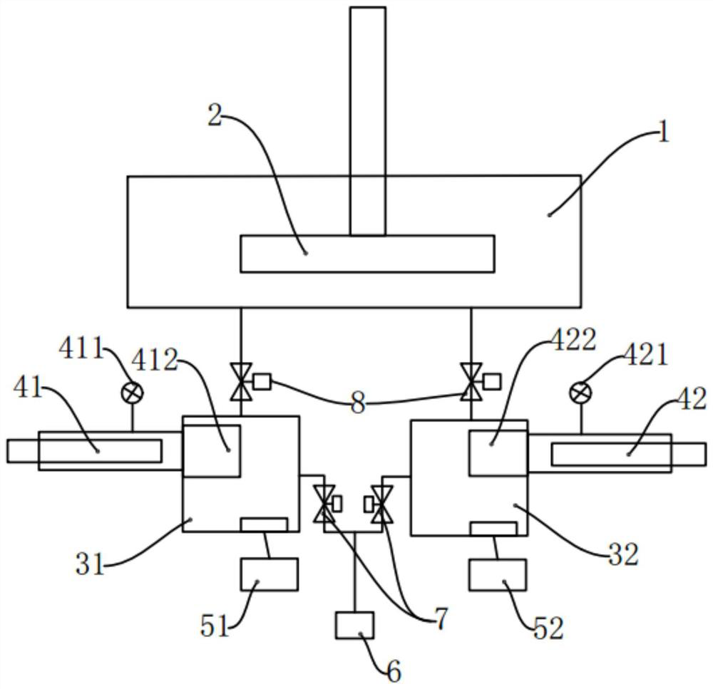
[0039] see figure 2 , which is a schematic block diagram of Embodiment 2 of the continuous delivery system for solid-liquid mixture materials of the present invention. It is further optimized on the basis of Embodiment 1.

[0040] In this embodiment, the first delivery branch includes a first plunger pump 41 and a first feeding chamber 31, and the first plunger pump 41 acts on the first feeding chamber 31 through a first isolation device 412 to generate Volume changes for feeding and feeding. The first isolating device 412 is a bellows. When the first conveying branch discharges, the first plunger pump 41 pushes inward, and the bellows expands in the first feeding chamber 31, so that the first feeding chamber 31 The volume decreases, and the materials in the first feeding cavity 31 are pushed out. The first isolation device 412 may also be an isolation film. Through the setting of the isolation device, the isolation between the plunger pump and the material can be realize...

Embodiment 3

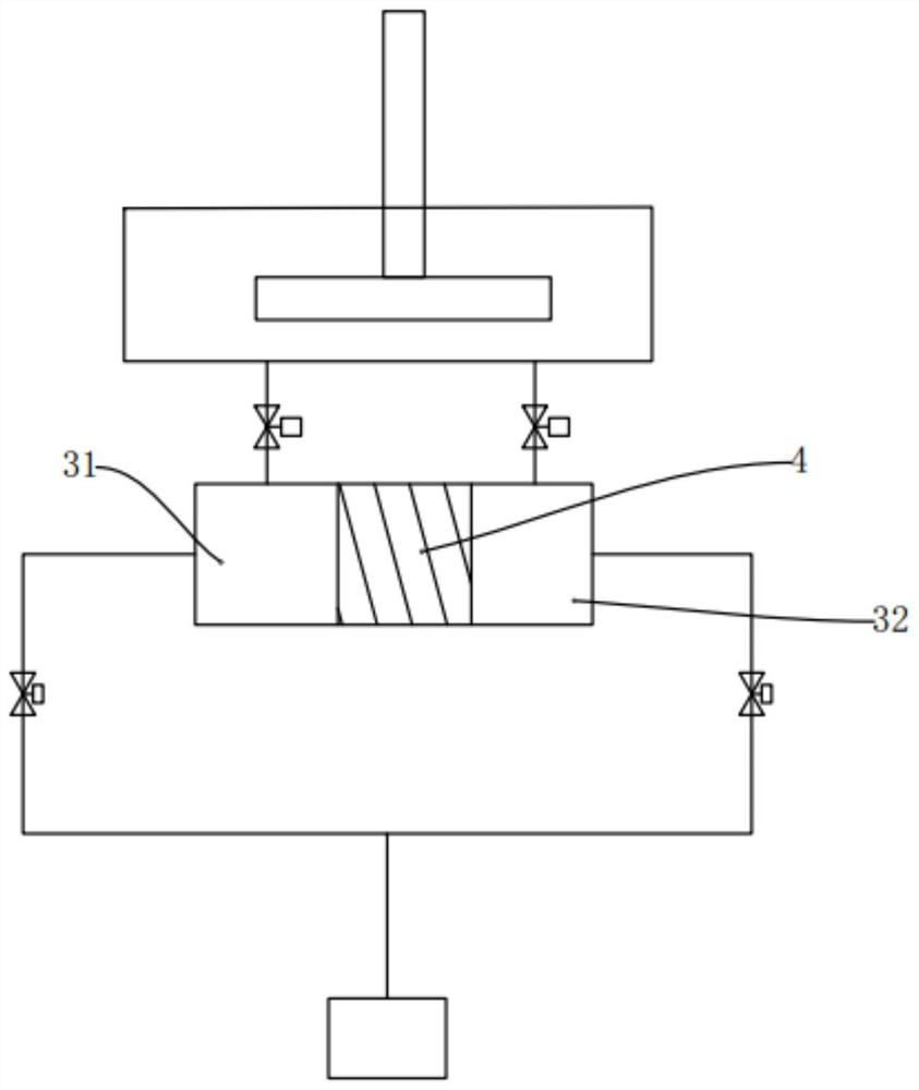
[0045] see image 3 , which is a schematic block diagram of Embodiment 3 of the continuous conveying system for solid-liquid mixture materials of the present invention. The main difference between it and Embodiment 2 lies in the part of the pushing device. There are two pushing devices in the second embodiment, that is, the first plunger pump and the second plunger pump; and there is one pushing device 4 in this embodiment.

[0046] Specifically, the pushing device 4 is placed in the feeding chamber, and divides the space in the feeding chamber into a first feeding chamber 31 and a second feeding chamber 32 , one left and one right. The pushing device 4 can reciprocate left and right in the feeding chamber, so that the volumes of the first feeding chamber 31 and the second feeding chamber 32 on both sides of the pushing device 4 in the feeding chamber increase or decrease. For example image 3 As shown, when the pushing device 4 moved to the left, the volume of the first fee...


PUM


Abstract

The invention discloses a continuous conveying system for solid-liquid mixed materials. The continuous conveying system comprises a discharging main path, a first conveying branch path and a second conveying branch path, the first conveying branch path and the second conveying branch path are mutually independent and are used for discharging and feeding according to a set period, when the first conveying branch path is used for discharging, the second conveying branch path is used for feeding, and when the second conveying branch path is used for discharging, the first conveying branch path is used for feeding; and the first conveying branch path and the second conveying branch path alternately communicate with the discharging main path through a discharging switching valve, the first conveying branch path and the second conveying branch path are in communication with the discharging main path in respective discharging periods and are cut off from the discharging main path in respective feeding periods, so that the discharging main path keeps continuously conveying materials, the pulse is small, the conveying efficiency is high, and the product service life is long. The invention further discloses a continuous conveying method for the solid-liquid mixed materials.

Description

technical field [0001] The invention relates to the technical field of material conveying, in particular to a continuous conveying system and method for solid-liquid mixed materials. Background technique [0002] In the prior art, there is a solution of using a plunger pump or a gear pump for high-pressure material transportation. The plunger pump has the advantages of equal pressure conveying and isolated conveying between the pump and the material. However, because the plunger pump has a return stroke, it cannot realize continuous conveying of the material, and intermittent material conveying will result in large conveying pulses and poor material conveying effect. it is good. The gear pump can realize the continuous conveying of the material and the pulse is small, but the gear pump cannot realize the isolation from the material; especially when the material is a solid-liquid mixed material, the solid particles in the mixed material will seriously wear the gear in the ge...

Claims


Application Information

Patent Timeline
Patent Type & Authority Applications(China)
IPC IPC(8): B65G53/52B65G53/66
CPCB65G53/52B65G53/66
Inventor 孔桂昌
Owner 杭州精进科技有限公司
Why Eureka
Try Eureka