Al technical title is built by PatSnap Al team. It summarizes the technical point description of the patent document.
A rammer and functional technology, applied in the field of road construction, can solve the problems of easily polluting the surrounding environment, endangering the health of users, reducing the quality of ramming, etc., so as to reduce the probability of stuck phenomenon and reduce the use of energy. , the effect of improving safety and reliability
Inactive Publication Date: 2021-06-29
南京极雨环保科技有限公司
View PDF0 Cites 2 Cited by
Summary
Abstract
Description
Claims
Application Information
AI Technical Summary
This helps you quickly interpret patents by identifying the three key elements:
Problems solved by technology
Method used
Benefits of technology
Problems solved by technology
[0003] When the existing tamping machine tamps the ground, the tamping plate will generate a large vibration when it is in contact with the ground, which is very prone to dusty phenomena, pollutes the surrounding environment, and easily causes the dust to be absorbed by the human body. Inhalation, thereby endangering the health of the user and reducing the safety of the existing ramming machine, not only that, after the existing ramming machine rams the ground, the soil is easy to adhere to the bottom of the ramming plate, making the ramming The bottom of the plate is uneven, which leads to unevenness on the ground after the ramming plate has been compacted, thereby reducing the quality of the ramming and reducing the reliability of the ramming machine
Method used
Image
Click on the blue label to locate the original text in one second.
Reading with bidirectional positioning of images and text.
Examples
Embodiment Construction
[0027] The present invention is described in further detail now in conjunction with accompanying drawing. These drawings are all simplified schematic diagrams, which only illustrate the basic structure of the present invention in a schematic manner, so they only show the configurations related to the present invention.
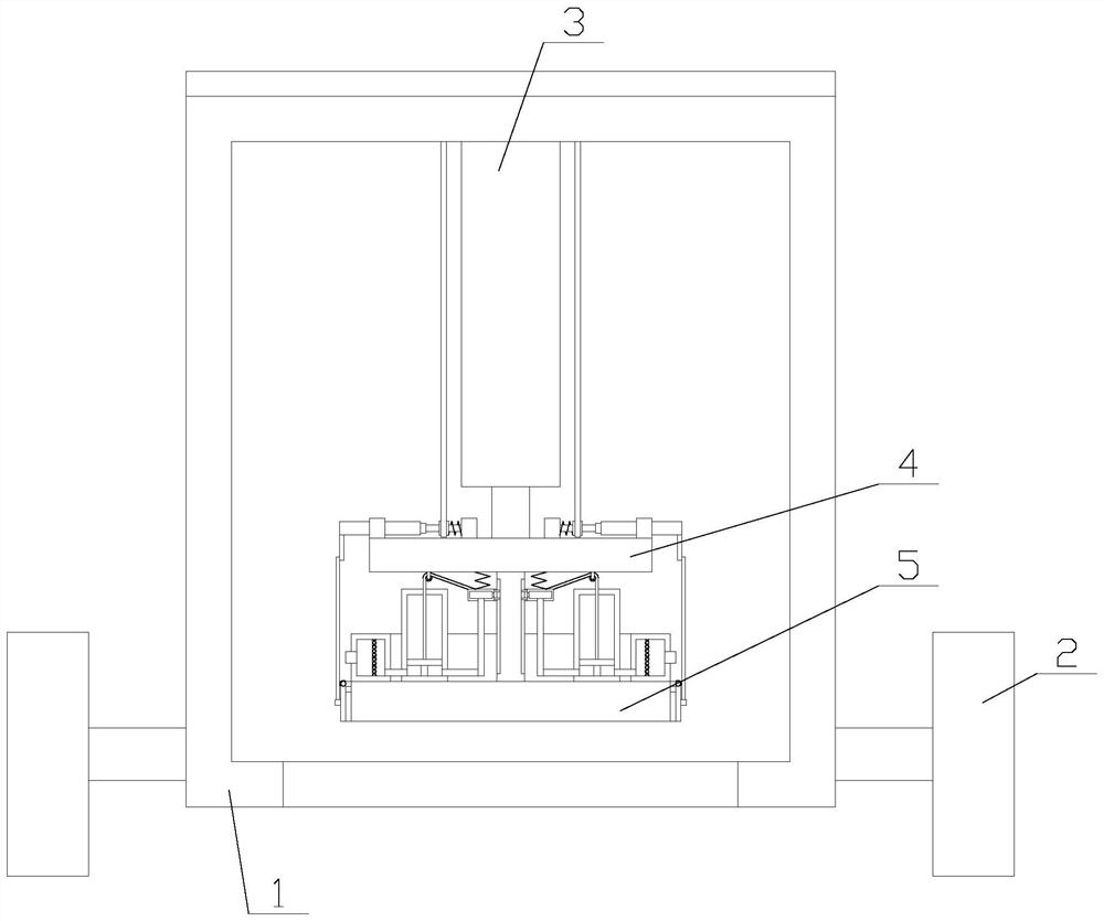
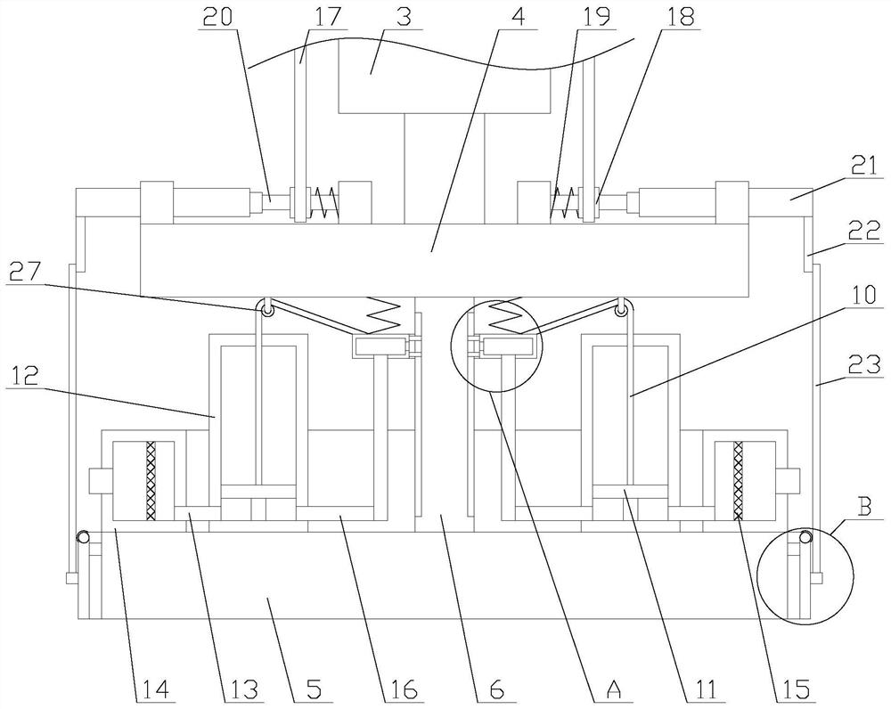
[0028] Such as figure 1 As shown, a tamping machine with a dust-absorbing function includes a main body 1, a cylinder 3, a support plate 4, a fixed rod 6, a tamping plate 5 and two moving devices 2, and the two moving devices 2 are respectively arranged on the sides of the main body 1. On both sides, the cylinder body of the cylinder 3 is vertically arranged on the top of the main body 1, the support plate 4 and the ramming plate 5 are horizontally arranged inside the main body 1, and the ramming plate 5 is arranged under the support plate 4 , the air rod of the cylinder 3 is connected to the upper center of the support plate 4, and the two ends of the fixed ...
PUM
Abstract
The invention relates to a tamping machine with a dust collection function. The tamping machine comprises a main body, an air cylinder, a support plate, a fixed rod, a tamping plate, two moving devices, a dust collection mechanism and two auxiliary mechanisms, wherein the dust collection mechanism comprises a dust collection box, a filter screen, a moving box, two limiting assemblies, two power assemblies and a plurality of first springs, and the auxiliary mechanisms comprise rotating shafts, rotating discs, pull ropes, first torsion springs, one-way bearings, driving shafts, driving rods, vibration assemblies and two first bearings. According to the tamping machine with the dust collection function, through the dust collection mechanism, the dust collection function is realized, the amount of dust inhaled by a human body is reduced, and the harm to the body health of a user is prevented; and through the auxiliary mechanisms, after tamping is completed, the tamping plate is vibrated, so that soil adhered to the lower part of the tamping plate can be shaken off, the function of cleaning the tamping plate is realized, the soil is prevented from being accumulated on the lower part of the tamping plate, the phenomenon that the tamped ground is uneven is avoided, and the tamping plate is not influenced.
Description
technical field [0001] The invention relates to the field of road construction, in particular to a rammer with dust suction function. Background technique [0002] The tamping machine is a compaction machine that uses impact and impact vibration to tamp backfill soil layer by layer. At the same time, the impact and shock vibration can also be used to break the road surface layer by layer, and it is mostly used for leveling and compacting the foundation during construction. [0003] When the existing tamping machine tamps the ground, the tamping plate will generate a large vibration when it is in contact with the ground, which is very prone to dusty phenomena, pollutes the surrounding environment, and easily causes the dust to be absorbed by the human body. Inhalation, thereby endangering the health of the user and reducing the safety of the existing ramming machine, not only that, after the existing ramming machine rams the ground, the soil is easy to adhere to the bottom o...
Claims
Application Information
Patent Timeline
Application Date:The date an application was filed.
Publication Date:The date a patent or application was officially published.
First Publication Date:The earliest publication date of a patent with the same application number.
Issue Date:Publication date of the patent grant document.
PCT Entry Date:The Entry date of PCT National Phase.
Estimated Expiry Date:The statutory expiry date of a patent right according to the Patent Law, and it is the longest term of protection that the patent right can achieve without the termination of the patent right due to other reasons(Term extension factor has been taken into account ).
Invalid Date:Actual expiry date is based on effective date or publication date of legal transaction data of invalid patent.