Layer-by-layer building wall sewage treatment system and treatment method

A sewage treatment system and wall technology, applied in biological water/sewage treatment, water/sludge/sewage treatment, construction, etc., can solve problems affecting the living environment, leaving stains, breeding bacteria, etc., to prevent the accumulation of scale , reduce the growth of bacteria, realize the effect of automation and intelligent control

Inactive Publication Date: 2021-06-29
贵州工业职业技术学院
View PDF0 Cites 0 Cited by
  • Summary
  • Abstract
  • Description
  • Claims
  • Application Information

AI Technical Summary

Problems solved by technology

[0002] The water supply system and drainage system in the construction project, the building water supply project is a combination of a series of engineering facilities that supply domestic water, production water and fire-fighting water within the community and inside the building. The building water supply system can be divided into three categories according to the purpose: life Water supply system, production water supply system and fire-fighting water supply system, the drainage system in construction engineering is divided into two parts: building internal drainage and building external drainage. The rainwater drainage system is divided into ordinary external drainage system and gutter external drainage system according to whether there is a gutter on the roof, while the internal drainage of the building is to set up a separate sewage discharge structure in each individual room according to the number of floors. In this kind of domestic sewage discharge structure, on the one hand, there will be a problem of blockage. On the other hand, during the process of domestic sewage flowing inside the sewage pipe, it will leave stains on the inner wall of the sewage pipe, which will breed bacteria and affect the living environment. Therefore, , in order to solve this kind of problem, we propose a sewage treatment system and treatment method on the wall of layered buildings

Method used


Image

  • Layer-by-layer building wall sewage treatment system and treatment method
  • Layer-by-layer building wall sewage treatment system and treatment method
  • Layer-by-layer building wall sewage treatment system and treatment method

Examples


Embodiment Construction

[0029] The following will clearly and completely describe the technical solutions in the embodiments of the present invention with reference to the accompanying drawings in the embodiments of the present invention. Obviously, the described embodiments are only some, not all, embodiments of the present invention.

[0030] In describing the present invention, it should be understood that the terms "upper", "lower", "front", "rear", "left", "right", "top", "bottom", "inner", " The orientation or positional relationship indicated by "outside", etc. is based on the orientation or positional relationship shown in the drawings, and is only for the convenience of describing the present invention and simplifying the description, rather than indicating or implying that the referred device or element must have a specific orientation, so as to Specific orientation configurations and operations, therefore, are not to be construed as limitations on the invention.

[0031] refer to Figure ...


PUM


Abstract

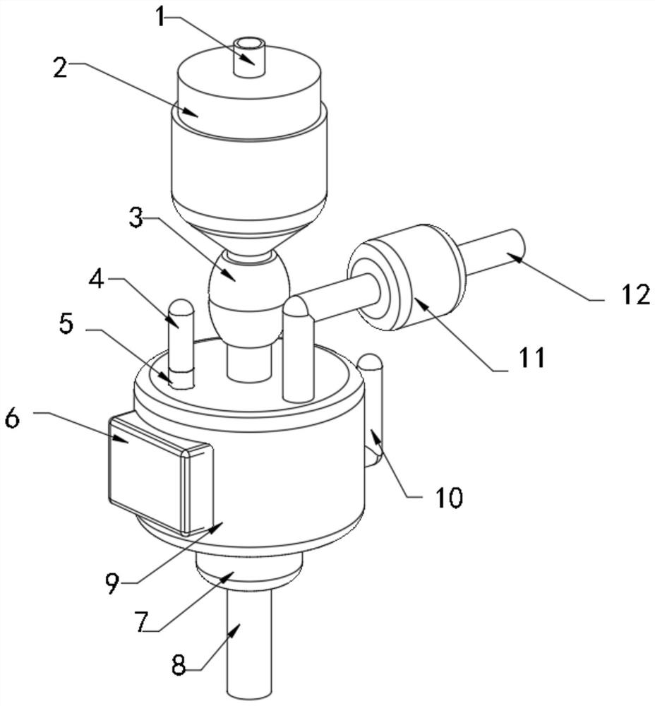
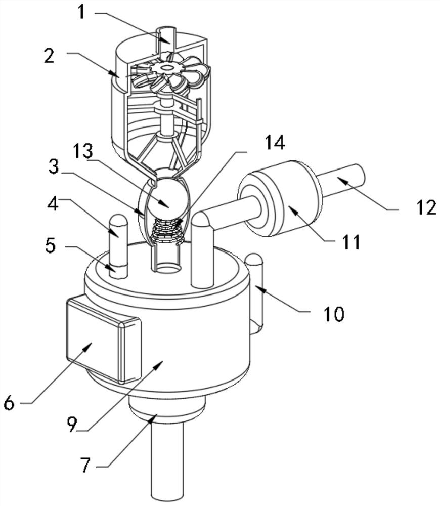
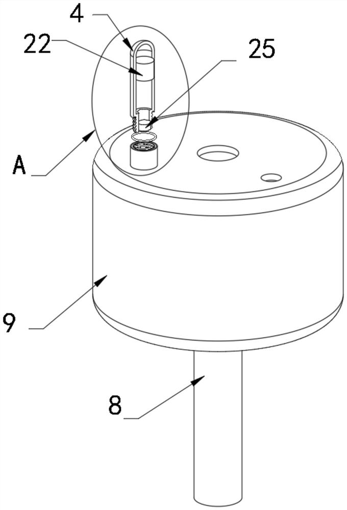
The invention discloses a layer-by-layer building wall sewage treatment system and treatment method. The layer-by-layer building wall sewage treatment system comprises a transfer bin, a digestion cavity is fixedly installed at the lower end of the transfer bin, a blocking bin is fixedly installed between the transfer bin and the digestion cavity, a water inlet pipeline and a water outlet pipeline are fixedly installed in the center of the upper surface of the transfer bin and the center of the lower surface of the digestion cavity, a supporting ring frame is fixedly installed on the inner wall of the transfer bin, a connecting rod is rotatably installed in the supporting ring frame, an installation base table is fixedly installed at the upper end of the connecting rod, connecting ring sleeves are symmetrically and fixedly installed on the connecting rod, and turbine fan blades are evenly distributed and fixedly installed on the outer wall of the circumference of the installation base table. According to the sewage treatment system, independent spaces are arranged layer by layer and used for treating sewage, in the sewage treatment process, the sewage treatment process is carried out in an anaerobic digestion mode, bacteria and peculiar smells generated in the sewage accumulation process can be reduced, and the treatment effect is remarkable.

Description

technical field [0001] The invention relates to the technical field of sewage treatment, in particular to a sewage treatment system and a treatment method for the walls of layered buildings. Background technique [0002] The water supply system and drainage system in the construction project, the building water supply project is a combination of a series of engineering facilities that supply domestic water, production water and fire-fighting water within the community and inside the building. The building water supply system can be divided into three categories according to the purpose: life Water supply system, production water supply system and fire-fighting water supply system, the drainage system in construction engineering is divided into two parts: building internal drainage and building external drainage. The rainwater drainage system is divided into ordinary external drainage system and gutter external drainage system according to whether there is a gutter on the roo...

Claims


Application Information

Patent Timeline
Patent Type & Authority Applications(China)
IPC IPC(8): E03C1/12E03C1/122E03C1/126E03C1/302F03B13/00C02F3/28
CPCC02F3/28C02F3/2806E03C1/12E03C1/1222E03C1/126E03C1/302F03B13/00
Inventor 冉全
Owner 贵州工业职业技术学院
Why Eureka
Try Eureka