
Combustion chamber, engine and aircraft based on supersonic speed ramjet oblique detonation

A combustor and supersonic technology, which is applied in deflagration combustors, combustion chambers, machines/engines, etc., can solve the problems of increasing total pressure loss, oblique detonation wave front propagation, and difficulty in detonation at small angles, achieving enhanced detonation and reduced Effect of total pressure loss and improvement of thermal cycle efficiency

Pending Publication Date: 2021-06-29
NAT UNIV OF DEFENSE TECH
View PDF7 Cites 0 Cited by
  • Summary
  • Abstract
  • Description
  • Claims
  • Application Information

AI Technical Summary

Problems solved by technology

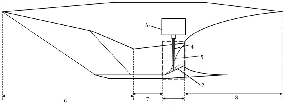
[0004] Existing oblique detonation engine schemes generally use a slope with a fixed angle to induce oblique detonation wave initiation in the supersonic incoming flow. It is difficult to detonate at a small angle, and it is easy to cause the forward propagation of the oblique detonation wave at a large angle, especially at present. In the case of Mach flow, it is even more difficult to achieve the stagnation of the detonation wave
Even if the oblique detonation wave can stagnate at a large angle, it will significantly increase the total pressure loss and significantly reduce the thermodynamic cycle efficiency of the oblique detonation engine. Therefore, the detonation initiation and stagnation of the detonation wave at a small angle slope are important in the current experimental research. question

Method used


Image

  • Combustion chamber, engine and aircraft based on supersonic speed ramjet oblique detonation
  • Combustion chamber, engine and aircraft based on supersonic speed ramjet oblique detonation
  • Combustion chamber, engine and aircraft based on supersonic speed ramjet oblique detonation

Examples


Embodiment Construction

[0021] The following will clearly and completely describe the technical solutions in the embodiments of the present invention with reference to the accompanying drawings in the embodiments of the present invention. Obviously, the described embodiments are only part of the embodiments of the present invention, not all of them. Based on the embodiments of the present invention, all other embodiments obtained by persons of ordinary skill in the art without creative efforts fall within the protection scope of the present invention.

[0022] The technical solutions of the various embodiments of the present invention can be combined with each other, but it must be based on the realization of those skilled in the art. When the combination of technical solutions is contradictory or cannot be realized, it should be considered that the combination of such technical solutions does not exist , nor within the scope of protection required by the present invention.

[0023] refer to Figure...


PUM


Abstract

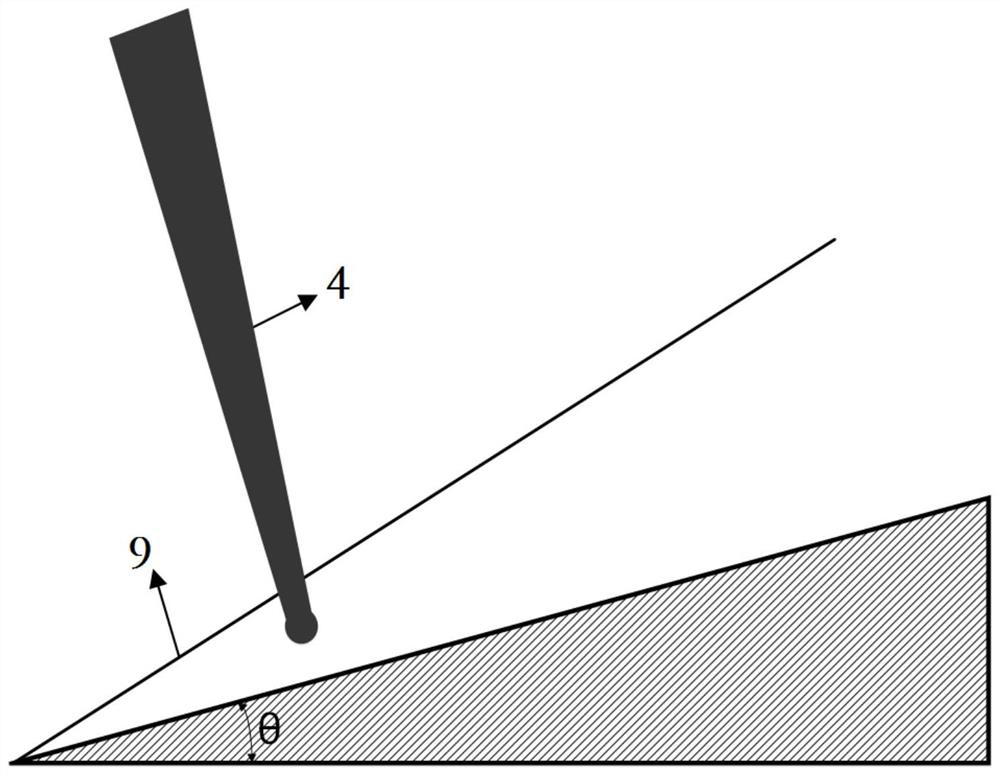
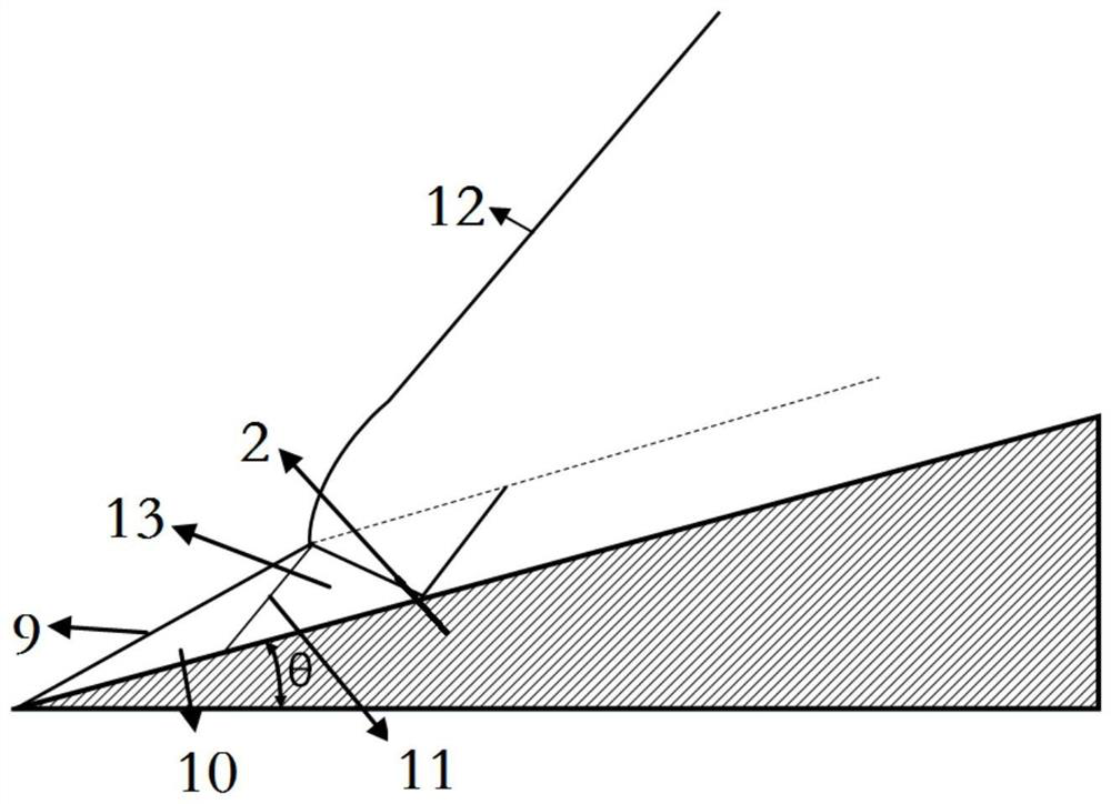
The invention discloses a combustion chamber, an engine and an aircraft based on supersonic speed ramjet oblique detonation. The combustion chamber is internally provided with a slope, the slope is obliquely arranged upwards from the inlet end of the combustion chamber to the outlet end of the combustion chamber, and one side wall face, opposite to the slope, of the combustion chamber is provided with a high-energy laser emitting device; the high-energy laser emitting device can emit laser and focus lasers after inducing oblique shock waves above the slope, the focused laser serves as a high-energy ignition source, energy is injected into a flow field, premixed gas is ignited, and therefore oblique detonation wave detonation is promoted. According to the combustion chamber, high-energy lasers and a small-angle physical slope are combined, high-energy laser focusing is utilized under the condition of slope induction, ignition is carried out after oblique shock wave induction, and therefore oblique detonation wave detonation can be effectively promoted.

Description

technical field [0001] The invention belongs to the technical field of hypersonic propulsion, and more specifically relates to a combustion chamber, an engine and an aircraft based on supersonic ram oblique detonation. Background technique [0002] In recent years, the field of hypersonic propulsion has become a new field that is being pursued at home and abroad, and hypersonic vehicles have great development potential in the field of national defense and military affairs. At present, the scramjet engine based on the Brayton isobaric combustion cycle can achieve high Mach flight within a certain range, and great progress has been made in technology. However, due to the limitations of the combustion method itself, it is difficult to improve the efficiency of the thermodynamic cycle. The detonation engine has higher thermal cycle efficiency and faster heat release efficiency than the traditional scramjet engine, and also has the advantages of simple structure and small size. ...

Claims


Application Information

Patent Timeline
IPC IPC(8): F23R7/00F02C7/264F02K7/02
CPCF23R7/00F02C7/264F02K7/02
Inventor 袁雪强刘卫东刘世杰林志勇苗世坤张海龙张多
Owner NAT UNIV OF DEFENSE TECH
Learn More