

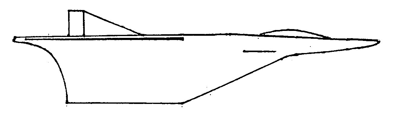
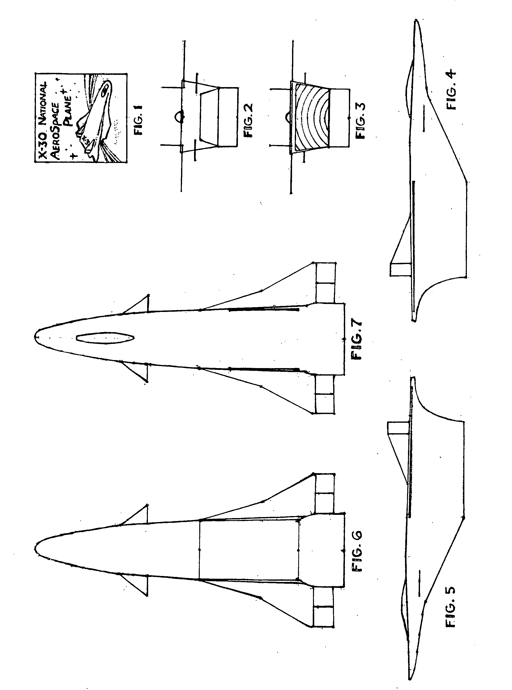
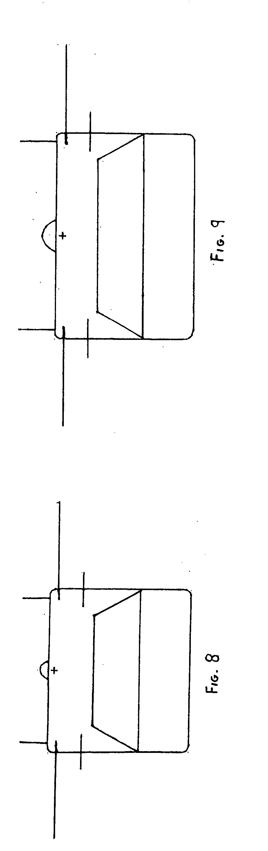
Hiigh wing monoplane aerospace plane based fighter.
a monoplane, fighter technology, applied in the field of aero/astronautics, can solve the problems of limited access to suborbital and orbital flight, cost of $10,000/lb., etc., and achieve the effect of improving the power-to-weight ratio
- Summary
- Abstract
- Description
- Claims
- Application Information
AI Technical Summary
Problems solved by technology
Method used
Image

Examples
Embodiment Construction
[0047] The present invention advances the art and is practical due to its materials and configuration. The primary material is titanium aluminide, referred to hereafter as TiAl that is for the first time in its development history systematically forged and extruded toward the F-102 50,000 ton for forgings and 12,000 ton extrusion press weight baselines for duralumin established while developing the first production supersonic interceptor. These materials improve weights and operating costs and payloads go up dramatically as a portion of GTW, producing order of magnitude improvements in performance and payload cost per pound, as demonstrated by modern fighters to Mach 2.7 and the advent of commercial jet transport. Approaching and exceeding the prior press weight benchmarks utilizing TiAl makes flight from Mach 3.5 to orbit and beyond, cost effective and practical. Improved thermal efficiency through compacted metallic structures facilitates approach to design thermal limits of 2500-...
PUM
 Abstract
Description
Claims
Application Information