Core burning for scramjet engines

a scramjet engine and core technology, applied in the engine field, can solve the problems of increasing costs and complexity, difficult to sustain combustion, etc., and achieve the effects of reducing the length of the scramjet combustor, and reducing the heat load of the combustor

Inactive Publication Date: 2008-04-24
AEROJET ROCKETDYNE INC
View PDF17 Cites 24 Cited by
  • Summary
  • Abstract
  • Description
  • Claims
  • Application Information

AI Technical Summary

Benefits of technology

[0013]It is an advantage of certain aspects of the invention that flame front arrival at the wall of the scramjet combustor is delayed thereby reducing combustor heat load. A further advantage of certain aspects of the invention is that by combining in-stream injection of fuel with a lean (fuel-poor) outer annulus, the bulk of combustion is confined to the scramjet combustor center. This concept, referred to as “core-burning,” further reduces combustor heat load.
[0014]Among the benefits of the core-burning embodiments of the invention are the scramjet combustor length may be reduced when instream injection is utilized. Further, the fuel injectors may be spaced for zone injection. In-stream injection is recognized as effective to reduce the combustor length relative to wall only injection resulting in reduced viscous losses and heat load within the combustor. Combustor hot spots are minimized or eliminated simplifying cooling requirements and may reduce or eliminate the need for an endothermic heat sink.

Problems solved by technology

The high velocity and low pressure flow of air and fuel, within the main combustor 18 makes it difficult to sustain combustion.
As a result, the walls must be made from exotic high temperature resistant materials such as tungsten or actively cooled with scarce fuel increasing costs and complexity.

Method used


Image

  • Core burning for scramjet engines
  • Core burning for scramjet engines
  • Core burning for scramjet engines

Examples


first embodiment

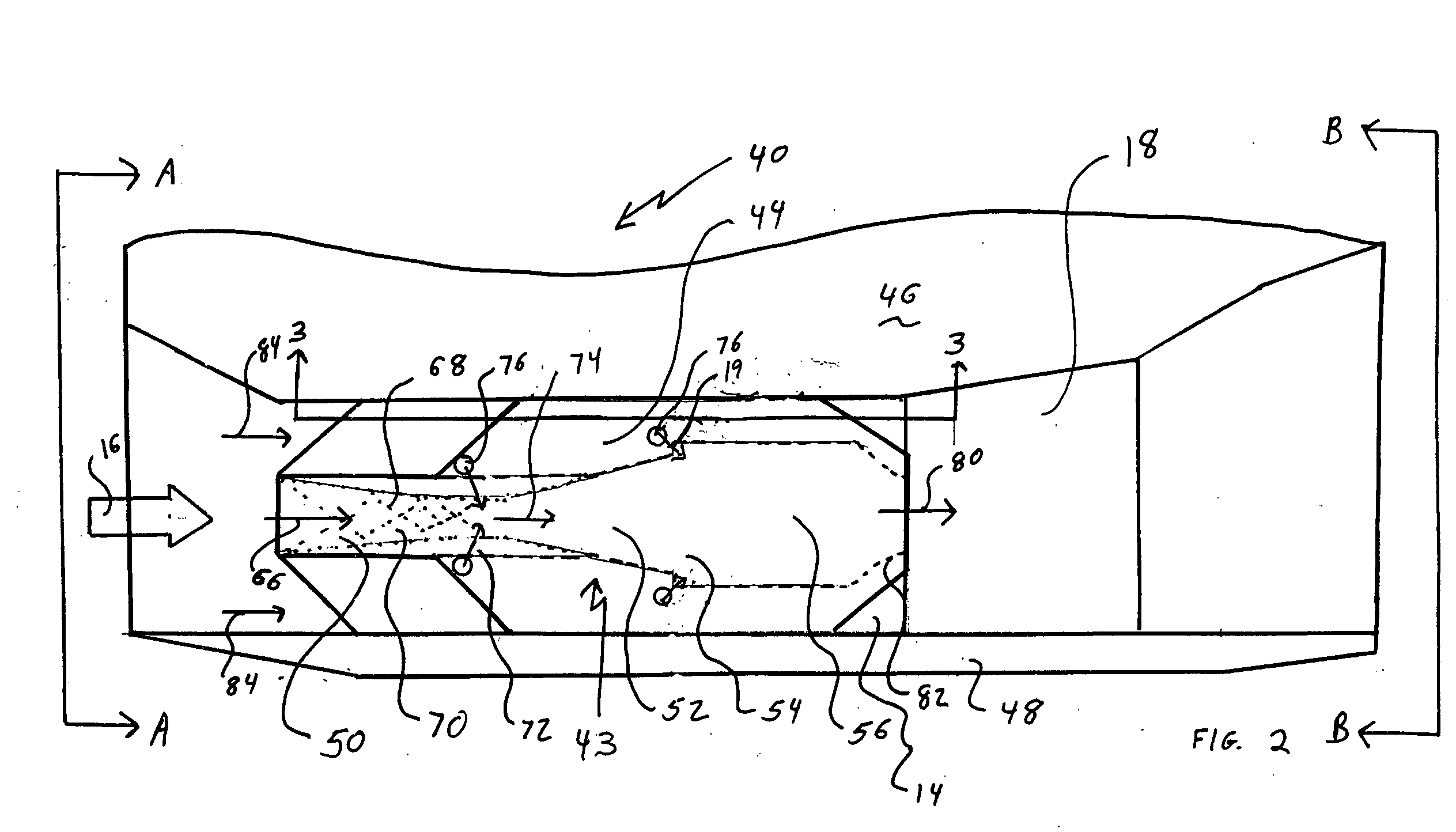
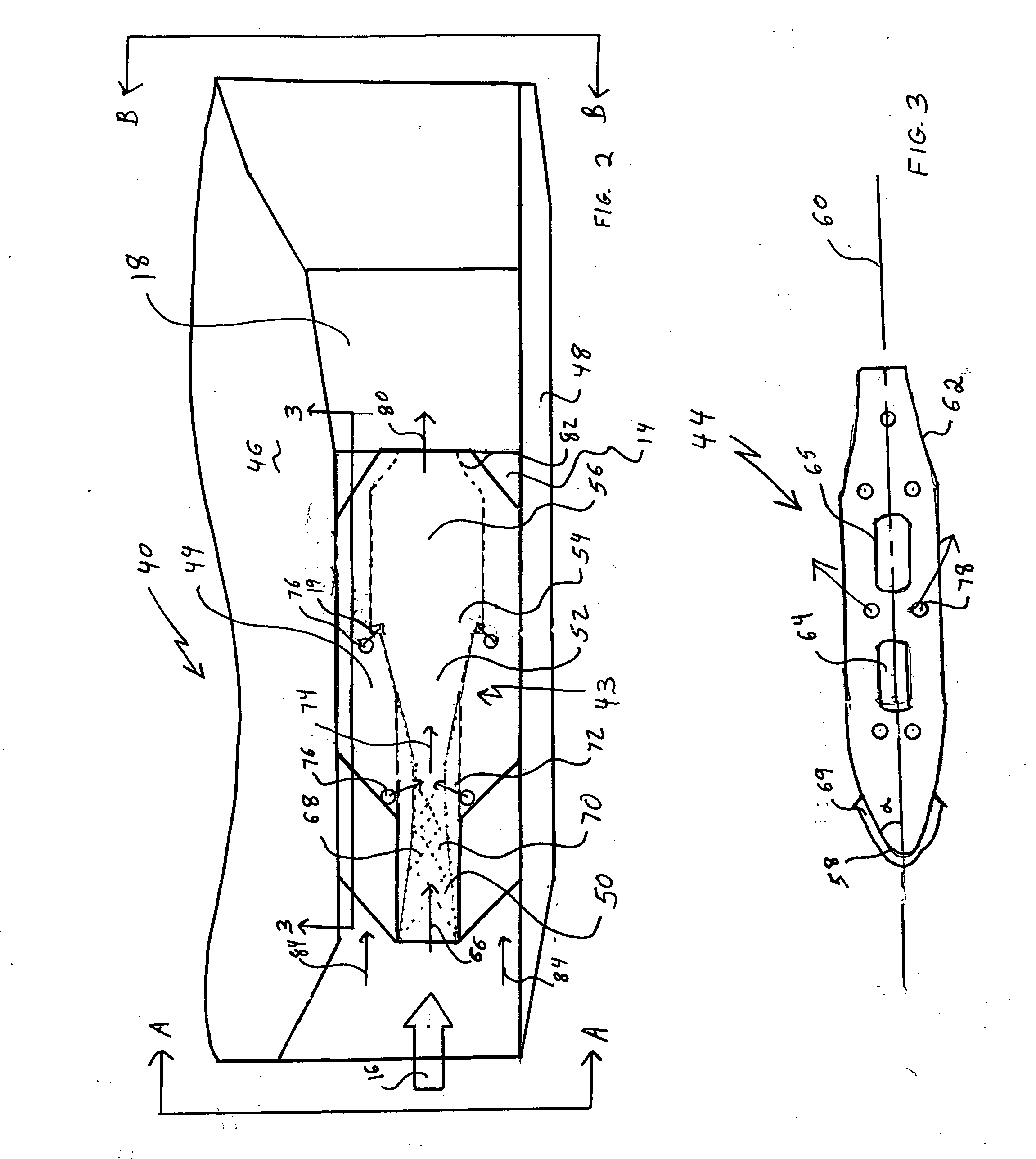
[0028]FIG. 2 illustrates a 2-D scramjet module 40 having a strut pilot 43 in accordance with the invention. The strut pilot 43 is fully contained within strut 44 that bridges a gap within the main isolator 14 extending between a body side 46 of a vehicle, such as a missile or the like and a cowl side 48. The strut 44 mounted strut pilot 43 includes a pilot isolator 50, a pilot diffuser 52, a pilot flameholder 54, a pilot combustor 56 and a pilot nozzle 82. It is noted that the strut pilot 43 is essentially a ramjet fully contained within strut 44. As illustrated in cross-sectional representation in FIG. 3, the strut 44 has a small leading edge radius 58 and a wedge shaped windscreen 69 that forms a relatively small angle, α, relative to a center line axis 60 to minimize air drag through the main isolator of the scramjet module. Trailing edge 62 is formed by a tapered boat tail shape with a similar angle relative to the centerline axis and may have bluff base for enhanced strength. T...

second embodiment

[0036]In accordance with the invention, FIG. 8 illustrates a main isolator 14 for a scramjet having an axisymmetric cross-sectional profile. A centerbody pilot pod 42 is mounted with axial symmetry along a center line axis of the scramjet. The centerbody pilot pod 42 includes a pilot isolator 50, pilot diffuser 52, pilot flameholder 54 and pilot combustor 56 and is essentially a dual mode ramjet (DMRJ) symmetrically disposed within the scramjet main isolator 14. In operation, the pilot receives pilot portion air 66 from the scramjet intake 16. The pilot portion air 66 is slowed in pilot isolator 50 by shock train 68 and further slowed in the pilot diffuser 52. Pilot fuel injectors 76 add fuel to the pilot portion air stream which is ignited by the pilot flameholder 54 and burned in the pilot combustor 56. The hot exhaust 80 exits the pilot pod to ignite the fuel and air mixture flowing around the centerbody pilot pod 42. The centerbody pilot pod 42 is supported by a plurality of str...


PUM


Abstract

A pilot for a scramjet provides a flame front whose arrival at the wall of the scramjet combustor is delayed thereby reducing combustor heat load. By combining in-stream injection of fuel with an interior pilot and a lean (fuel-poor) outer annulus, the bulk of combustion is confined to the scramjet combustor center. This concept, referred to as “core-burning,” further reduces combustor heat load. One such pilot is for a two dimensional scramjet effective to propel a vehicle. This pilot includes a plurality of spaced apart struts separated by ducts and a strut pilot contained within each strut. A second such pilot is for an axisymmetric scramjet engine has, in sequence and in fluid communication, an air intake, an open bore scramjet isolator and a scramjet combustor. This centerbody pilot pod includes a pilot isolator disposed between the air intake and a pilot diffuser, the pilot diffuser disposed between the pilot isolator and a pilot with the pilot disposed between the pilot diffuser and a pilot combustor. The pilot pod is in axis symmetry around a central axis of the scramjet isolator and supported by a plurality of struts extending from an inner wall of the open bore to an outer surface of the centerbody pilot pod.

Description

CROSS REFERENCE TO RELATED APPLICATION(S)[0001]N.A.U.S. GOVERNMENT RIGHTS[0002]N.A.BACKGROUND OF THE INVENTION[0003]1. Field of the Invention[0004]This invention relates to an engine that utilizes air moving at supersonic speeds for compression, combustion and expansion. Such an engine is known as a scramjet. More particularly, a pilot pod is centrally disposed within an isolator of a scramjet module. As a result, the hottest combustion gases are located within the core of the combustor, rather than along the walls, thereby reducing combustor heat load.[0005]2. Description of the Related Art[0006]Engines that use ram compression instead of a mechanical compressor to pressurize air for combustion and expansion are known as ramjets. When the flowpath through the engine is designed specifically for higher speeds where supersonic combustion is superior, that is typically at speeds above Mach 5 or 6, the engine is referred to as a scramjet. A simplified version of a prior art scramjet is...

Claims


Application Information

Patent Timeline
Patent Type & Authority Applications(United States)
IPC IPC(8): B64G1/40
CPCF02K7/10
Inventor BULMAN, MELVIN J.
Owner AEROJET ROCKETDYNE INC
Why Eureka
Try Eureka