All-optical shaper, method and device for determining parameters of all-optical shaper

A light shaper and parameter technology, which is applied in the direction of instruments, optics, optical components, etc., can solve the problems of not being able to meet the performance requirements of shaping, and achieve the effects of ensuring long-distance effective transmission, enriching implementation methods, and optimizing parameters

Active Publication Date: 2022-04-08
GUANGXUN SCI & TECH WUHAN
View PDF3 Cites 0 Cited by
  • Summary
  • Abstract
  • Description
  • Claims
  • Application Information

AI Technical Summary

Problems solved by technology

[0003] In related technologies, there are certain limitations in the selection of the shaper structure and the optimization of parameters, and the signal shaped by the shaper is a PAM signal with equal power intervals, which cannot meet the shaping performance requirements on each level.

Method used


Image

  • All-optical shaper, method and device for determining parameters of all-optical shaper
  • All-optical shaper, method and device for determining parameters of all-optical shaper
  • All-optical shaper, method and device for determining parameters of all-optical shaper

Examples


Embodiment Construction

[0073] The technical solutions of the present invention will be further described in detail below in conjunction with the accompanying drawings and specific embodiments.

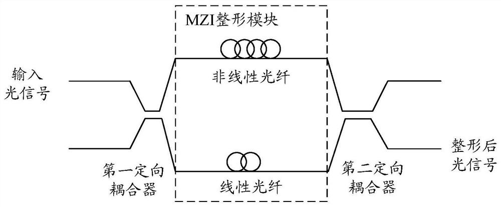
[0074] An embodiment of the present invention provides a plenoptic shaper, such as figure 1 as shown, figure 1 It is a schematic structural diagram of an all-optical shaper provided by an embodiment of the present invention, including:

[0075] MZI shaping module, a first directional coupler and a second directional coupler; wherein, the MZI shaping module includes: an upper arm and a lower arm arranged side by side with the upper arm;

[0076] The output ends of the first directional coupler are respectively connected to the input ends of the MZI shaping module for decomposing the input optical signal into two optical signals; performing a nonlinear phase shift on one of the optical signals in the two optical signals, and performing a linear phase shift on one of the optical signals in the two optical sig...


PUM


Abstract

Embodiments of the present invention provide a plenoptic shaper and a method and device for determining parameters of the plenoptic shaper. The shaper includes: an MZI shaping module, a first directional coupler and a second directional coupler; wherein, the MZI shaping module includes: an upper arm and a lower arm arranged side by side with the upper arm; the output of the first directional coupler The terminals are respectively connected to the input terminals of the MZI shaping module, which are used to decompose the input optical signal into two optical signals; and carry out nonlinear phase shift on one optical signal in the two optical signals through the upper arm, and perform nonlinear phase shift on the optical signal of the two optical signals through the lower arm. One of the two optical signals mentioned above is linearly phase-shifted; the input end of the second directional coupler is connected to the upper arm and the lower arm of the MZI shaping module, and is used to couple the two optical signals output by the upper arm and the lower arm to obtain shaping after the optical signal.

Description

technical field [0001] The invention relates to the technical field of optical fiber communication, in particular to an all-optical shaper and a method and device for determining parameters of the all-optical shaper. Background technique [0002] In the optical fiber communication system, the optical signal is easily affected by factors such as fiber dispersion, ASE noise accumulation of the optical amplifier, and interaction between channels during the transmission process, which leads to the degradation of the optical signal and ultimately limits the transmission rate of the system and the network. In order to ensure the reliable transmission of information in the network, it is necessary to regenerate the degraded signal in time. [0003] In related technologies, there are certain limitations in the selection of the shaper structure and the optimization of parameters, and the signal shaped by the shaper is a PAM signal with equal power intervals, which cannot meet the sha...

Claims


Application Information

Patent Timeline
Patent Type & Authority Patents(China)
IPC IPC(8): G02B27/09
CPCG02B27/0994
Inventor 孔祥健徐晓辉张博胡毅罗勇
Owner GUANGXUN SCI & TECH WUHAN
Why Eureka
Try Eureka