
Metal plate polishing device

A technology of metal plates and vertical plates, applied in the direction of grinding drive devices, grinding/polishing safety devices, metal processing equipment, etc., can solve the burns and cracks on the workpiece surface, affect the processing quality of the workpiece surface, and affect the grinding effect on the surface of the grinding wheel and other issues to achieve the effect of reducing impact and alleviating thermal recession

Active Publication Date: 2021-07-02
唐山替欧特种金属制品有限公司
View PDF5 Cites 0 Cited by
  • Summary
  • Abstract
  • Description
  • Claims
  • Application Information

AI Technical Summary

Problems solved by technology

[0002] When the grinding wheel commonly used in engineering is grinding or cutting materials, it often generates a lot of grinding heat due to friction, which easily causes problems such as burns and cracks on the surface of the workpiece. Seriously affect the surface processing quality of the workpiece
[0003]In the prior art, most of them use the method of increasing the heat dissipation area or changing the configuration of the grinding wheel for heat transfer, and the passive heat dissipation method is used to achieve the purpose of heat dissipation; The problem of thermal attenuation affecting the grinding effect

Method used


Image

  • Metal plate polishing device
  • Metal plate polishing device
  • Metal plate polishing device

Examples


Embodiment Construction

[0025] The following will clearly and completely describe the technical solutions in the embodiments of the present invention with reference to the accompanying drawings in the embodiments of the present invention. Obviously, the described embodiments are only some, not all, embodiments of the present invention. Based on the embodiments of the present invention, all other embodiments obtained by persons of ordinary skill in the art without creative efforts fall within the protection scope of the present invention.

[0026] In describing the present invention, it is to be understood that the terms "opening", "upper", "lower", "thickness", "top", "middle", "length", "inner", "surrounding" etc. Indicating orientation or positional relationship is only for the convenience of describing the present invention and simplifying the description, and does not indicate or imply that the components or elements referred to must have a specific orientation, be constructed and operated in a sp...


PUM


Abstract

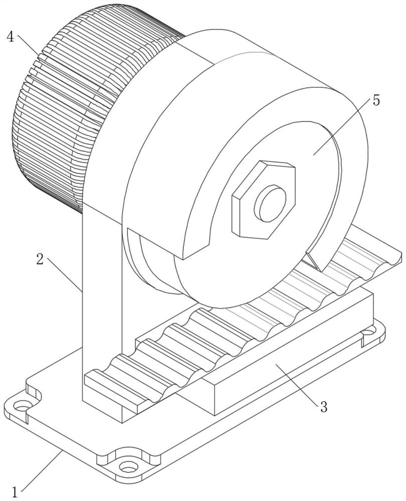
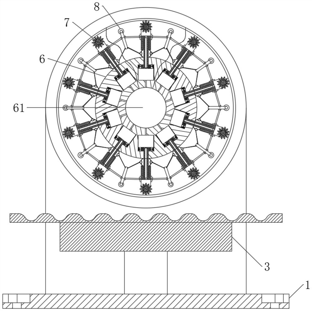
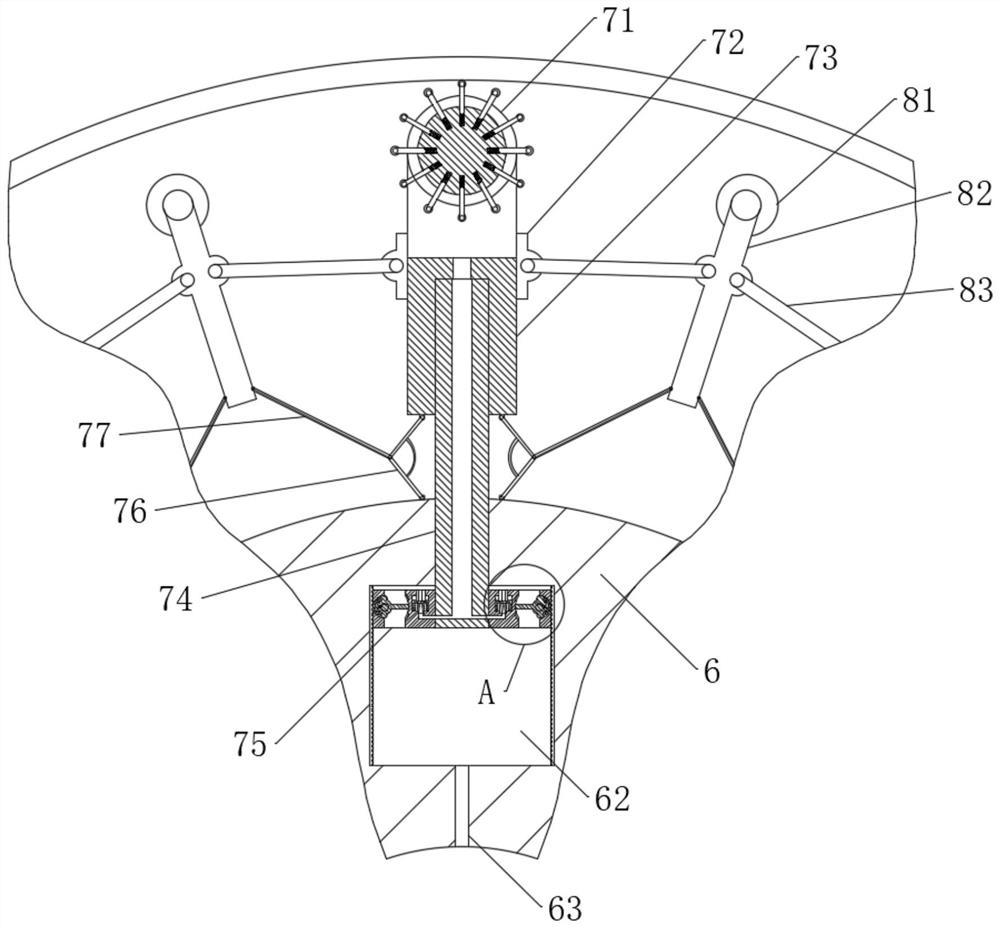
The invention discloses a metal plate polishing device, and relates to the technical field of metal machining machines. The metal plate polishing device comprises a base, wherein a vertical plate is vertically arranged on the base, a motor is fixedly installed on the vertical plate, a polishing disc is fixedly installed on a rotating shaft of the motor, a bracket is arranged on the lower side of the polishing disc, the polishing disc comprises a rotating wheel, first supporting columns and second supporting columns, a through hole is formed in the middle of the rotating wheel, a plurality of cavities are annularly distributed in the rotating wheel, the cavities are located on the outer side of the through hole, and meanwhile the cavities communicate with the through hole through communicating grooves; and a plurality of telescopic first supporting columns are installed on the rotating wheel in a sliding mode, the ends of the first supporting columns extend into the cavities, and meanwhile every two adjacent first supporting columns are connected through the corresponding second supporting column. According to the metal plate polishing device, when the surface of a workpiece and the polishing disc are extruded, the first supporting columns are pushed to contract, installation frames in the contracted first supporting columns push elastic connecting rods to contract, the contracted elastic connecting rods push two pull rods to be gathered together, and therefore the second supporting columns are pushed to extend out, an abrasive belt is tensioned through the extending-out elastic connecting rods, and the problem that the abrasive belt is loosened and falls off in the contracting process is avoided.

Description

technical field [0001] The invention belongs to the technical field of metal processing machinery, in particular to a metal plate grinding device. Background technique [0002] Grinding wheels commonly used in engineering often generate a lot of grinding heat due to friction when grinding or cutting materials, which can easily cause burns and cracks on the surface of the workpiece, seriously affecting the surface processing quality of the workpiece. [0003] In the prior art, most of them adopt the method of increasing the heat dissipation area or changing the configuration of the grinding wheel for heat transfer, and the passive heat dissipation method is used to achieve the purpose of heat dissipation; in addition, the heat attenuation on the surface of the grinding wheel affects the grinding effect. Contents of the invention [0004] The purpose of the present invention is to provide a metal plate grinding device. When the surface of the workpiece is squeezed with the g...

Claims


Application Information

Patent Timeline
IPC IPC(8): B24B21/12B24B21/18B24B21/20B24B41/00B24B47/00B24B55/02
CPCB24B21/12B24B21/18B24B21/20B24B41/007B24B55/02B24B47/00
Inventor 张燕苹
Owner 唐山替欧特种金属制品有限公司
Learn More