Supercharge Your Innovation With Domain-Expert AI Agents!

Mold pressing equipment

An equipment and molding technology, applied in the direction of presses, material forming presses, manufacturing tools, etc., can solve problems such as inconvenience in demoulding, and achieve the effect of avoiding too tight combination, good use effect, and improving separation convenience.

Pending Publication Date: 2021-07-02
GUANGDONG POWER GRID CO LTD +1
View PDF5 Cites 0 Cited by
  • Summary
  • Abstract
  • Description
  • Claims
  • Application Information

AI Technical Summary

Problems solved by technology

[0004] In view of this, the present invention provides a molding equipment, which is used to solve the problem of inconvenient demoulding of traditional molding equipment

Method used


Image

  • Mold pressing equipment
  • Mold pressing equipment
  • Mold pressing equipment

Examples


Embodiment 1

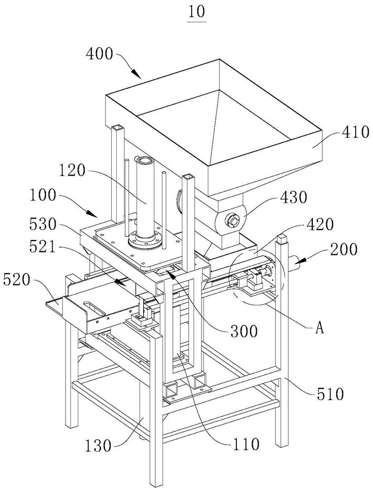
[0053] refer to figure 1 As shown, the present invention provides a molding equipment 10, which includes a compacting device 100, a moving device 200 and a frame 500; the frame 500 is used as an installation carrier for fixedly installing the compacting device 100 and the moving device 200, The device 100 is used for accommodating raw materials and performing pressing operation to form a green body, and can drive the green body to move onto the frame 500 , and the moving device 200 is used to transport the green body on the frame 500 .

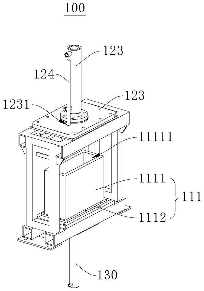
[0054] Specifically, the frame 500 is provided with a feeding hole 521, and the frame 500 is used to carry the green body; please continue to refer to image 3 and Figure 4The compact device 100 includes a mold mechanism 110, a compact assembly 120 and an ejector assembly 130. The mold mechanism 110 is provided with a cavity 11111 connected to the feed hole 521. The compact assembly 120 and the mold mechanism 110 are relatively movable, and ...

Embodiment 2

[0086] This embodiment also provides a molding device 10. This embodiment is basically the same as Embodiment 1, and the symbol meanings are the same as Embodiment 1. Only the differences are listed below:

[0087] refer to figure 1 As shown, the molding equipment 10 of this embodiment also includes a demoulding mechanism 300, which is movable relative to the frame 500; the demoulding mechanism 300 is internally provided with a liquid storage chamber 311 for accommodating the demoulding agent, and the demoulding mechanism The mechanism 300 is provided with a liquid discharge hole 312 that communicates with the liquid storage chamber 311; the moving device 200 is used to drive the demoulding mechanism 300 to move, so that the liquid discharge hole 312 is connected to or disconnected from the mold cavity 11111; the mobile device 200 also It is used to transport the green body output from the cavity 11111.

[0088] In the molding equipment 10 of this embodiment, by setting the d...


PUM


Abstract

The invention provides mold pressing equipment. The equipment is characterized by comprising a blank pressing device, a demolding mechanism and a moving device; the blank pressing device comprises a mold mechanism and a blank pressing assembly, the mold mechanism is provided with a mold cavity used for containing blank pressing raw materials, and the blank pressing assembly and the mold mechanism are relatively movably arranged and used for pressing the raw materials in the mold cavity to form a blank body; the demolding mechanism and the blank pressing device are relatively movably arranged; a liquid storage cavity used for containing a release agent is formed in the demolding mechanism, and a liquid drainage hole communicating with the liquid storage cavity is formed in the demolding mechanism; the moving device is used for driving the demolding mechanism to move, so that the liquid discharge hole communicates with or is disconnected from the mold cavity; the moving device is further used for conveying the blank body output by the mold cavity. According to the mold pressing equipment, the moving function of the demolding mechanism is achieved through cooperation with the moving device, the injection operation of the release agent is achieved on the premise that normal pressing operation is not affected, then the separation convenience of the blank body and the mold mechanism is improved, and the use effect is good.

Description

technical field [0001] The invention relates to the technical field of environmental protection equipment, in particular to a molding equipment. Background technique [0002] In waste soil recycling projects currently on the market, in order to facilitate waste soil recycling, molding equipment is usually used to suppress waste soil. Molding equipment is mainly composed of turntable machines, vacuum extruders, hydraulic molding machines and other hosts. [0003] In traditional molding equipment, after the molding is completed, the green body and the mold are tightly combined, and it is difficult to separate. Usually, the mold needs to be removed to take out the green body. The operation is very inconvenient, which seriously affects the processing efficiency and use effect of the molding equipment. In order to change this situation, it is necessary to design a new molding equipment. Contents of the invention [0004] In view of this, the present invention provides a moldin...

Claims


Application Information

Patent Timeline
IPC IPC(8): B30B11/14B30B15/30B30B15/32B30B15/00
CPCB30B11/14B30B15/30B30B15/32B30B15/0005
Inventor 刘文松张宝星潘岐深郑松源陈彩娜张壮领毕明利莫一夫刘通庄毅谭国华赵伟东谢林兴杨先秦理黄澄吴伟智张裕达钟万国韩元兵黄利明周龙翔周腾
Owner GUANGDONG POWER GRID CO LTD
Features
  • R&D
  • Intellectual Property
  • Life Sciences
  • Materials
  • Tech Scout
  • Unparalleled Data Quality
  • Higher Quality Content
  • 60% Fewer Hallucinations
Learn More