Automatic reinforcement binding robot for building construction
A technology of building construction and robots, which is applied in the fields of construction, building structure, and building materials processing, can solve the problems of high cost, increased operation risk, and low efficiency, so as to improve the operation accuracy and avoid the risk of manual binding Effect
- Summary
- Abstract
- Description
- Claims
- Application Information
AI Technical Summary
Problems solved by technology
Method used
Image


Examples
Embodiment Construction
[0022] The present invention will be described in further detail below in conjunction with the accompanying drawings, and the technical solutions in the embodiments of the present invention will be clearly and completely described. Apparently, the described embodiments are only some of the embodiments of the present invention, not all of them. Based on the embodiments of the present invention, all other embodiments obtained by persons of ordinary skill in the art without making creative efforts belong to the protection scope of the present invention.
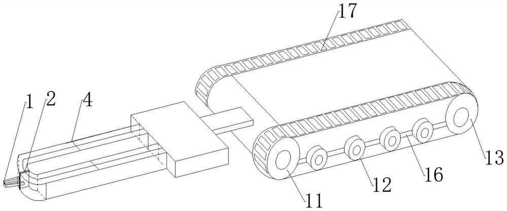
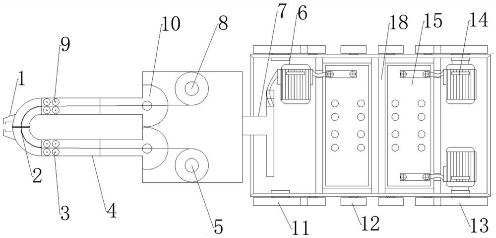
[0023] see Figure 1-Figure 7 , an automatic tendon binding robot, comprising a tendon binding mechanism, a walking mechanism, and an operating unit. The tendon binding mechanism is composed of four parts such as a wire cutter 1, a wire feeding module, a binding module, and a motor unit. The wire feeding module is characterized in that it includes The wire feeding wheel 3, the right material rack 5, the left material rack 8, th...
PUM
 Abstract
Description
Claims
Application Information