Distributed optical fiber sensor

A distributed optical fiber and optical fiber sensor technology, applied in the direction of converting sensor output, using optical devices to transmit sensing components, instruments, etc., can solve the problems of measurement interruption, increase measurement cost, shorten service life, etc., to reduce measurement cost, The effect of reducing measurement time and improving measurement accuracy

Inactive Publication Date: 2021-07-02
QINGYUAN POWER SUPPLY BUREAU OF GUANGDONG POWER GRID CO LTD
View PDF4 Cites 0 Cited by
  • Summary
  • Abstract
  • Description
  • Claims
  • Application Information

AI Technical Summary

Problems solved by technology

[0003] However, in the prior art, when the distributed optical fiber sensor is used, the sensing optical fiber is directly welded to the surface of the object to be measured by welding. It is very easy to break during the process, which will cause the interruption of the measurement, which not only prolongs the measurement time, but also greatly increases the cost of the measurement; moreover, the optical fiber sensor has poor heat dissipation in the installation box, and some Open holes for heat dissipation, but at the same time, dust will enter the installation box, affecting the normal operation of the fiber optic sensor and shortening the service life

Method used


Image

  • Distributed optical fiber sensor
  • Distributed optical fiber sensor
  • Distributed optical fiber sensor

Examples


Embodiment 1

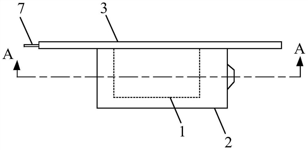
[0031] Such as figure 1 and figure 2 As shown, a distributed optical fiber sensor provided by an embodiment of the present invention includes an optical fiber sensor body 1 , a housing 2 and a metal substrate 3 .

[0032] Wherein, the fiber optic sensor body 1 can be a fiber optic sensor, and the fiber optic sensor is a sensor that converts the state of the measured object into a measurable optical signal. The interaction between the modulator and the external measured parameters changes the optical properties of the light, such as light intensity, wavelength, frequency, phase, polarization state, etc., and becomes a modulated optical signal, which is then sent to the optoelectronic device through the optical fiber. The parameters of the measured object are obtained after the demodulator.

[0033] The metal substrate 3 can be a flat metal plate, preferably a square aluminum plate, so that the aluminum plate has good electrical and thermal conductivity, and the aluminum plat...

Embodiment 2

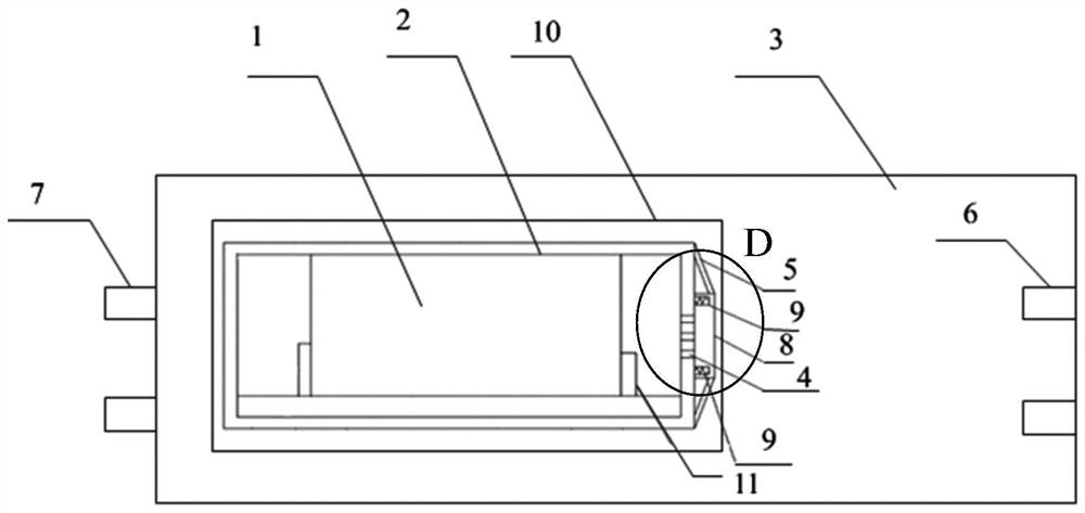
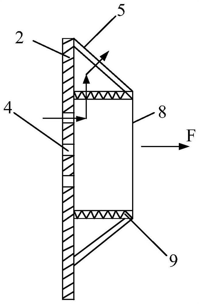
[0038] The embodiment of the present invention is optimized on the basis of the foregoing embodiment one, such as figure 1 and figure 2 As shown, a distributed optical fiber sensor provided by the embodiment of the present invention includes an optical fiber sensor body 1, a housing 2, and a metal substrate 3. The optical fiber sensor body 1 is fixed inside the housing 2, and the side wall of the housing 2 is provided with cooling holes. 4 and the filter screen 5 covering the cooling holes 4, the metal substrate 3 is provided with a mounting groove 10 and a welding groove, the shell 2 is connected to the metal substrate 3 through the mounting groove 10, and the metal substrate 3 is connected to the object to be measured through the welding groove.

[0039] Such as figure 2As shown, in an optional embodiment of the present invention, a fixing column 11 is provided in the housing 2, and the fixing column 11 is used to fix the fiber sensor body 1. Column 11, wherein, the sect...


PUM


Abstract

The embodiment of the invention discloses a distributed optical fiber sensor. The distributed optical fiber sensor comprises an optical fiber sensor body, a shell and a metal substrate; the optical fiber sensor body is fixed in the shell; heat dissipation holes and a filter screen are arranged on the side wall of the shell; a mounting groove and a welding groove are formed in the metal substrate; the mounting groove is used for mounting the shell; the welding groove is used for welding an object to be detected. According to the embodiment of the invention, the optical fiber sensor is fixed on the metal substrate through the shell, sensing optical fibers in the distributed optical fiber sensor are prevented from being broken in the use process, dust prevention and heat dissipation are realized through the heat dissipation holes and the filter screen, and the to-be-measured object is indirectly measured through the metal substrate, so that the sensing optical fibers are prevented from being broken, the measurement cost is reduced, heat dissipation and dust prevention can be achieved, the service life is prolonged, and the measurement precision of the distributed optical fiber sensor is improved.

Description

technical field [0001] Embodiments of the present invention relate to the technical field of optical fiber sensors, in particular to a distributed optical fiber sensor. Background technique [0002] Distributed optical fiber sensor is a sensor that uses unique distributed optical fiber detection technology to measure or monitor the spatial distribution and time-varying information along the optical fiber transmission path. It arranges the sensing fiber along the field, and can obtain the spatial distribution and time-varying information of the measured field at the same time, which is attractive for many industrial applications. [0003] However, in the prior art, when the distributed optical fiber sensor is used, the sensing optical fiber is directly welded to the surface of the object to be measured by welding. It is very easy to break during the process, which will cause the interruption of the measurement, which not only prolongs the measurement time, but also greatly i...

Claims


Application Information

Patent Timeline
Patent Type & Authority Applications(China)
IPC IPC(8): G01D5/26G01D5/353G01D11/24G01D11/16G01D11/00
CPCG01D5/268G01D5/353G01D11/245G01D11/16G01D11/00
Inventor 何伟明唐小亮潘斌张振黄绍川尹文阔于文滔黄富勇杨芳周亚兵王亮
Owner QINGYUAN POWER SUPPLY BUREAU OF GUANGDONG POWER GRID CO LTD
Why Eureka
Try Eureka