Quality and safety detection device and method for construction site

A safety detection and construction site technology, applied in electromagnetic wave transmission systems, electrical components, transmission systems, etc., can solve problems such as low work efficiency, waste, and unsmooth cable blowing, so as to improve work efficiency, save time, and facilitate on-site The effect of construction

Active Publication Date: 2021-07-02
西安西交费普瑞系统技术有限公司
View PDF9 Cites 0 Cited by
  • Summary
  • Abstract
  • Description
  • Claims
  • Application Information

AI Technical Summary

Problems solved by technology

At present, during on-site construction, it is necessary to bury the cable blowing pipe in advance, and then try to blow the optical cable into the pre-buried cable blowing pipe through the air blowing of the cable. When not moving, stop to check and solve the fault point before continuing to work, which wastes a lot of time and low work efficiency, so we need to pre-check whether the blowing cable is unobstructed. cable, so as to save time and improve work efficiency

Method used


Image

  • Quality and safety detection device and method for construction site
  • Quality and safety detection device and method for construction site

Examples


Embodiment 1

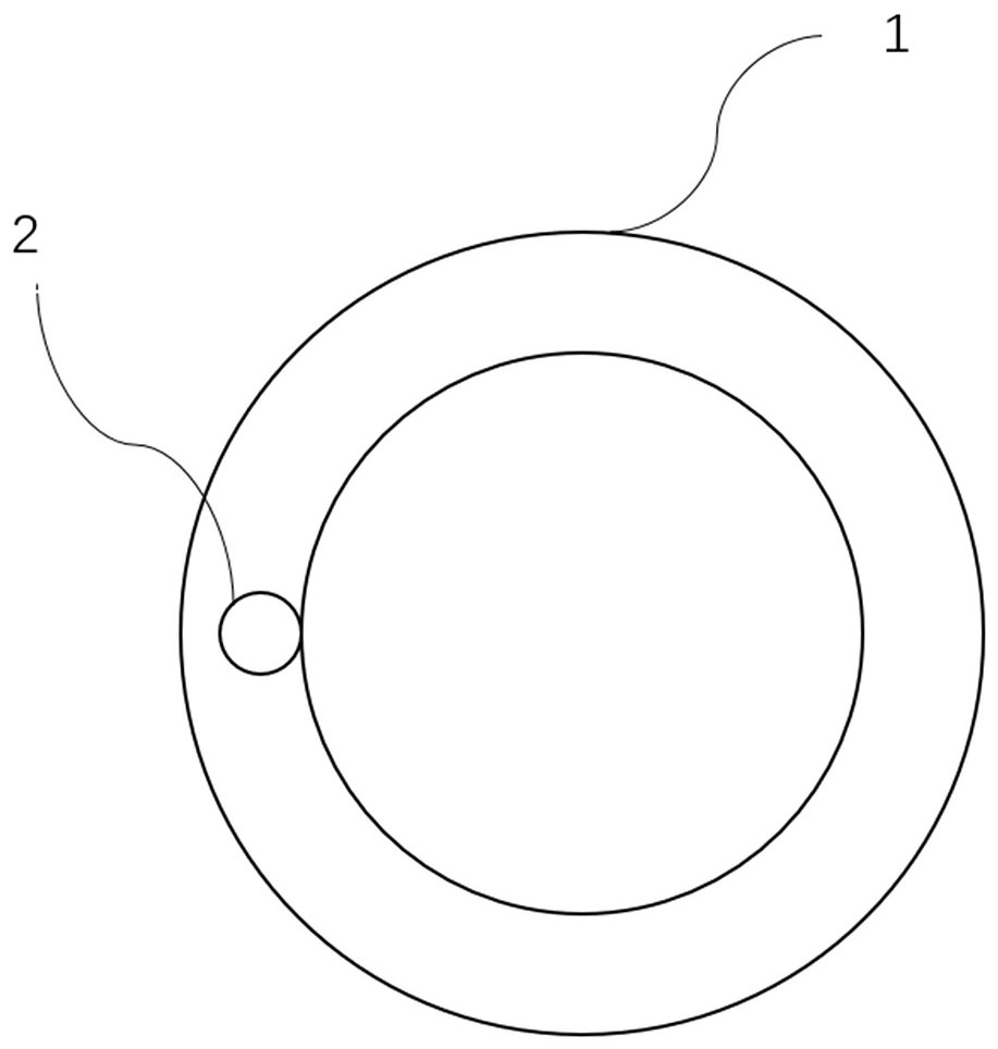
[0026] Figure 1-2 As shown, a technical scheme that the present invention adopts is: the quality of construction site, safety detection device, comprise blowing cable pipe 1, optical fiber 2, optical fiber union, optical time domain reflectometer; Described optical fiber 2 is arranged on blowing cable pipe 1 In the tube wall; the optical fiber 2 is connected with the optical fiber union; the optical time domain reflectometer is connected with the optical fiber union.

[0027] Preferably, the optical fiber 2 is arranged inside the pipe wall of the cable blowing pipe 1 .

[0028] Further, the length of the optical fiber 2 is greater than the length of the cable blowing pipe 1 , and the two ends of the optical fiber 2 are exposed from the two ends of the cable blowing pipe 1 .

[0029] Preferably, the optical time domain reflectometer can detect from both ends of the optical fiber 2 respectively.

[0030] Further, the optical time domain reflectometer is used to detect the dis...

Embodiment 2

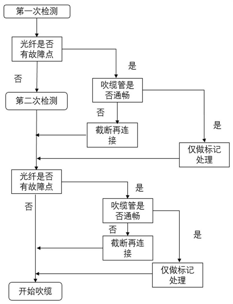
[0034] The present invention also provides a quality and safety detection method on the construction site, using the above-mentioned device, comprising the following steps:

[0035] Step 1. When distributing the disk, use the fusion splicer to make the optical fiber 2 and the optical fiber union hot-melt, connect the optical time domain reflectometer and the optical fiber union, and the optical time domain reflectometer first detects whether the optical fiber 2 in the cable blowing pipe 1 is If there is a fault point, if there is a fault point in the optical fiber 2, the optical time domain reflectometer will detect the distance between the fault point and the detection end, mark the position of the fault point and check whether the cable blowing tube 1 is unobstructed; if the cable blowing tube 1 is unobstructed, work The personnel only mark it; if the cable blowing pipe 1 is not smooth, the staff cuts off the unblocked cable blowing pipe 1, and then connects the two blowing c...


PUM


Abstract

The invention discloses a quality and safety detection device and method for a construction site. The quality and safety detection device comprises a cable blowing pipe, an optical fiber, an optical fiber movable joint and an optical time domain reflectometer, the optical fiber is arranged in the pipe wall of the cable blowing pipe; the optical fiber is connected with the optical fiber movable joint; and the optical time domain reflectometer is connected with the optical fiber movable joint. Whether the cable blowing pipe is smooth or not is detected in advance, if not, the cable blowing pipe can be processed in advance, and therefore time can be saved, and working efficiency can be improved.

Description

technical field [0001] The invention relates to the construction field, in particular to a quality and safety detection device and method at a construction site. Background technique [0002] Cable blowing is the air blowing method of optical cable, that is, the optical cable is blown into the pre-embedded blowing pipe by high-pressure air blowing. The cable blowing machine blows high-pressure, high-speed compressed air into the cable blowing pipe, and the high-pressure airflow pushes the air-sealing piston, so that the air-sealing piston connected to the end of the optical cable forms a settable uniform pulling force on the optical cable. At the same time, the blowing The hydraulic crawler conveying mechanism of the cable machine clamps the optical cable and conveys it forward to form a conveying force. The combination of pulling force and conveying force makes the penetrated optical cable quickly pass through the pipeline in a suspended state along with the high-speed airf...

Claims


Application Information

Patent Timeline
IPC IPC(8): H04B10/071
CPCH04B10/071
Inventor 周佳琪
Owner 西安西交费普瑞系统技术有限公司
Why Eureka
Try Eureka