Agricultural pollination unmanned aerial vehicle with efficient pollination function

A UAV and functional technology, applied in the field of UAV, can solve the problems of pollen damage, pollen collision with fan leaves, affecting pollination effect, etc.

Pending Publication Date: 2021-07-06
冯冬冬
View PDF2 Cites 5 Cited by
  • Summary
  • Abstract
  • Description
  • Claims
  • Application Information

AI Technical Summary

Problems solved by technology

[0003] At present, UAV pollination is mainly through the rotation of the fan to generate negative pressure, and then drive the pollen to spray out, but the rotation of the fan will cause the pollen to collide with the fan blades, which will easily cause damage to the pollen and affect its p...

Method used


Image

  • Agricultural pollination unmanned aerial vehicle with efficient pollination function
  • Agricultural pollination unmanned aerial vehicle with efficient pollination function
  • Agricultural pollination unmanned aerial vehicle with efficient pollination function

Examples


Embodiment 1

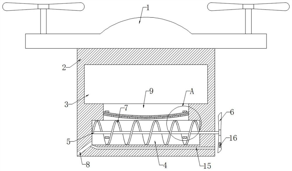
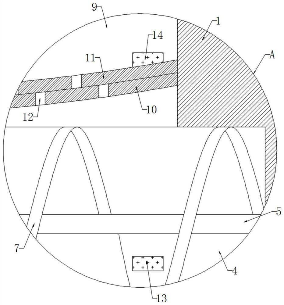
[0023] refer to Figure 1-2 , an agricultural pollination UAV with high-efficiency pollination function, comprising a body 1, a fixed block 2 is fixedly connected to the lower end of the body 1, a powder storage cavity 3 is opened in the fixed block 2, and a pushing cavity 4 is opened at the lower end of the fixed block 2, The inner wall of the pushing chamber 4 is rotatably connected with a rotating shaft 5, and the side wall of the rotating shaft 5 is fixedly connected with a spiral stirring blade 7, and the side wall of the spiral stirring blade 7 is sealed and rotatingly connected with the inner wall of the pushing chamber 4, so that the rotation of the spiral stirring blade 7 can rotate the The pollen in the cavity 4 is pushed out, and one end of the rotating shaft 5 runs through the side wall of the fixed block 2 and is fixedly connected with a plurality of impellers 6. The pushing cavity 4 is provided with a discharge hole 8 inclined downwards away from the inner wall of...

Embodiment 2

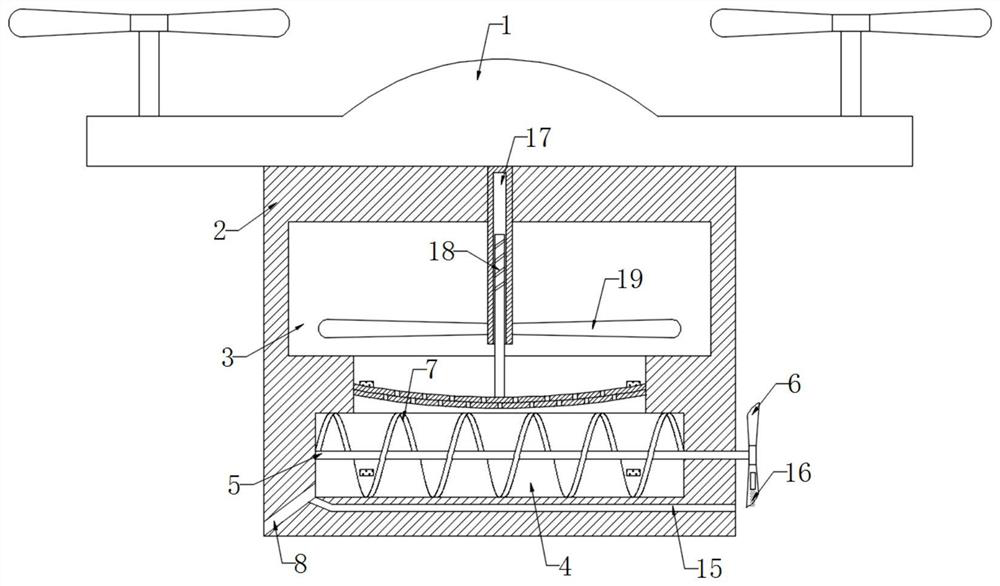
[0031] refer to image 3 , the difference from Embodiment 1 is that the inner top of the fixed block 2 is rotatably connected with a sleeve 17, the inner wall of the sleeve 17 is threadedly connected with a lead screw 18, the lower end of the lead screw 18 is fixedly connected with the upper end of the slide plate 11, and the lower end of the side wall of the sleeve 17 is fixed A plurality of stirring rods 19 are connected.

[0032] It should be noted that the thread distribution on the lead screw 18 is only located above the side wall of the lead screw 18 to prevent pollen from entering the threaded connection between the lead screw 18 and the inner wall of the sleeve 17, causing the sleeve 17 to be unable to rotate.

[0033] In this embodiment, when the slide plate 11 slides up and down, the lead screw 18 fixedly connected to the upper end of the slide plate 11 is driven to move up and down, and then the sleeve 17 screwed to the side wall of the lead screw 18 is driven to ro...


PUM


Abstract

The invention discloses an agricultural pollination unmanned aerial vehicle with an efficient pollination function. The agricultural pollination unmanned aerial vehicle comprises a vehicle body, a fixing block is fixedly connected to the lower end of the vehicle body, a pollen storage cavity is formed in the fixing block, a material pushing cavity is formed in the lower end of the fixing block, a rotating shaft is rotatably connected to the inner wall of the material pushing cavity, spiral stirring blades are fixedly connected to the side wall of the rotating shaft, the side walls of the spiral stirring blades are rotationally connected with the inner wall of the material pushing cavity in a sealed mode, and one end of the rotating shaft penetrates through the side wall of the fixing block and is fixedly connected with a plurality of impellers. When the machine body flies, the impellers rotate under the action of airflow, then the spiral stirring blades rotate, a permanent magnet intermittently gets close to and away from a permanent magnet block, the permanent magnet block slides up and down in a discharging opening, pollen in the pollen storage cavity enters the material pushing cavity through the discharging opening, then the spiral stirring blades rotate to push the pollen to flow out, the pollen can be discharged without rotation of a fan, and power consumption is reduced; and meanwhile, pollen damage caused by collision between the pollen and fan blades of the fan is avoided.

Description

technical field [0001] The invention relates to the technical field of unmanned aerial vehicle, in particular to an agricultural pollination unmanned aerial vehicle with efficient pollination function. Background technique [0002] When cultivating agricultural fruits, in order to increase the survival rate and growth quality of fruits, it is necessary to pollinate the stamens of fruit trees when they bloom. With the continuous development of agricultural technology, drone pollination is becoming more and more popular, which not only reduces the It reduces labor costs and increases pollination efficiency. [0003] At present, UAV pollination is mainly through the rotation of the fan to generate negative pressure, and then drive the pollen to spray out, but the rotation of the fan will cause the pollen to collide with the fan blades, which will easily cause damage to the pollen and affect its pollination effect, and the pollen is stored in the powder storage box After accumu...

Claims


Application Information

Patent Timeline
IPC IPC(8): A01H1/02B64D1/16
CPCB64D1/16B64U10/10B64U30/20B64U2101/00
Inventor 冯冬冬
Owner 冯冬冬
Why Eureka
Try Eureka