Chemical reagent leakage capturing and adsorbing device

A technology of adsorption device and reagent, applied in chemical/physical process, chemical/physical/physical-chemical process, packaging, etc., can solve the problems of loose connection of two pipes, pipe leakage, leakage and so on

Pending Publication Date: 2021-07-06
SHANDONG GUOTAI TECH
View PDF4 Cites 0 Cited by
  • Summary
  • Abstract
  • Description
  • Claims
  • Application Information

AI Technical Summary

Problems solved by technology

[0003] However, leakage accidents of chemical reagents often occur nowadays. For example, in existing storage tanks, the mouth of the storage tank is usually sealed with a screw cap. However, it may be bumped and vibrated during tr...

Method used


Image

  • Chemical reagent leakage capturing and adsorbing device
  • Chemical reagent leakage capturing and adsorbing device
  • Chemical reagent leakage capturing and adsorbing device

Examples


Embodiment 1

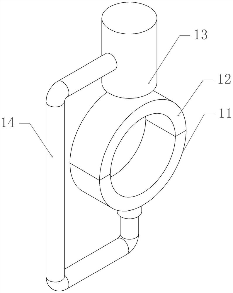
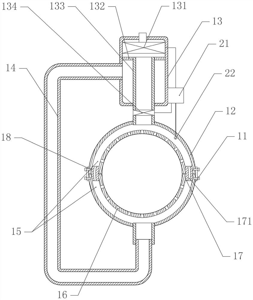
[0035] Basic as attached figure 1 And attached figure 2 Shown: a chemical reagent leakage capture and adsorption device, including a capture mechanism and an adsorption mechanism, the capture mechanism includes an upper ring 12 and a lower ring 11, the length of the upper ring 12 and the lower ring 11 is 20cm to 40cm, the length in this embodiment 25cm, the ends of the upper ring 12 and the lower ring 11 are fixed with sealing rings by screws, and the sealing rings are made of elastic materials in this embodiment. The inner side walls of the upper ring 12 and the lower ring 11 are provided with capture holes 16, and the upper ring 12 and the lower ring 11 are provided with a capture chamber 15, and the lower ring 11 is fixed with a sealing part 17, and the sealing part 17 extends into the upper ring In the capture cavity 15 of 12, a through hole 171 is opened on the closing part 17, and the through hole 171 communicates with the capture cavity 15 of the upper ring 12 and the...

Embodiment 2

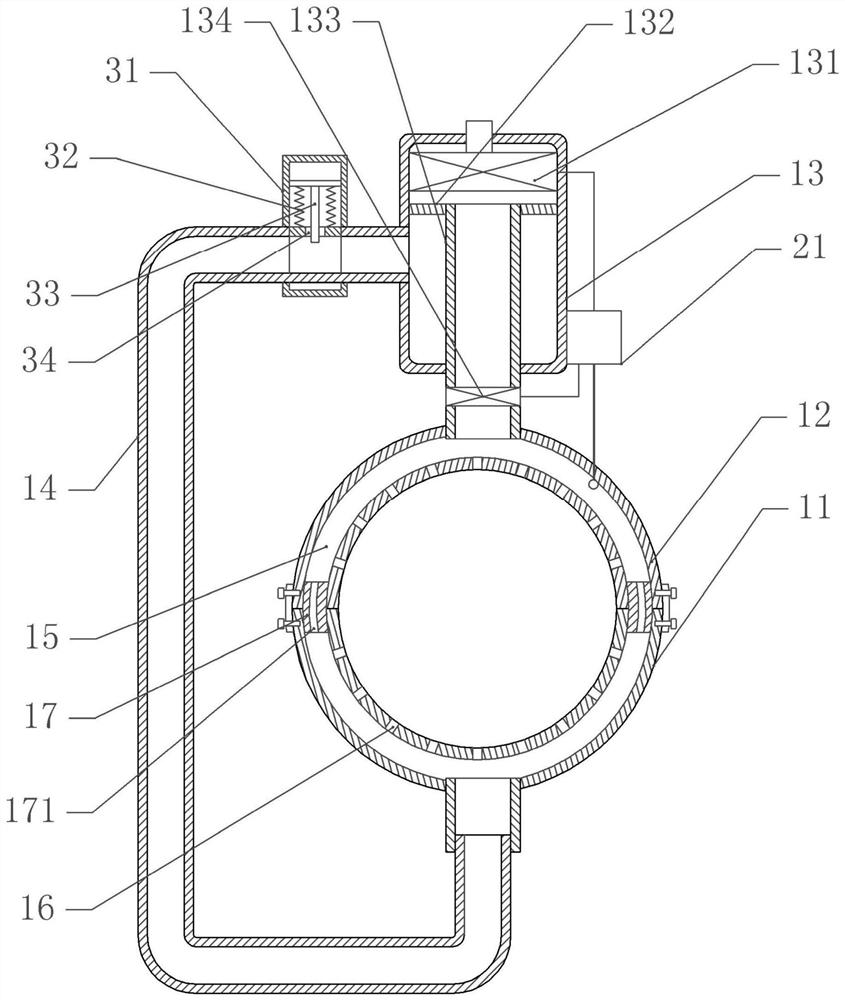
[0043] The difference between embodiment two and embodiment one is that, as attached image 3 As shown, an auxiliary detection mechanism is installed on the second pipeline 14. In this embodiment, the auxiliary detection mechanism includes a body 31, which is sleeved on the second pipeline 14 and fixed on the second pipeline 14 by bolts. There is a gap 34 on the second pipeline 14, and the second pipeline 14 communicates with the body 31 through the gap 34, and a detection plate is vertically slidably connected in the body 31, and the bottom screw of the detection plate is fixed with a closing plate for sealing the second pipeline 14 33. The closed pipe extends into the second pipe 14 through the gap 34. Both sides of the closed plate 33 are provided with springs 32. One end of the spring 32 is fixed on the detection plate, and the other end of the spring 32 is fixed on the second pipe 14. . In this embodiment, the body 31 is made of a transparent material, such as a transpar...

Embodiment 3

[0048] The difference between embodiment three and embodiment two is that, as attached Figure 4 As shown, the cavity is communicated with a second valve. In this embodiment, the second valve is a second solenoid valve 41. The second valve is communicated with a third pipeline 42. The third pipeline 42 is communicated with a water pump, and the water pump is electrically connected to the controller 21. . The second solenoid valve 41 is electrically connected to the controller 21 .

[0049] When the air pressure sensor 22 detects that the air pressure in the capture chamber 15 increases to indicate that a certain leakage has occurred at the connection position of the delivery pipeline or the storage tank, the controller 21 will control the second electromagnetic valve 41 to open, and control the water pump to the third pipeline 42. Transport the neutralizer, the neutralizer enters the cavity through the third pipeline 42, then enters the capture cavity 15 through the second pi...


PUM

PropertyMeasurementUnit
Lengthaaaaaaaaaa

Abstract

The invention discloses a chemical reagent leakage capturing and adsorbing device in the technical field of chemical reagent detection. The device comprises a capturing mechanism and an adsorbing mechanism, the capturing mechanism comprises an upper ring and a lower ring, the upper ring and the lower ring are connected through a connecting piece, capturing holes are formed in the inner side walls of the upper ring and the lower ring, and capturing cavities communicated with the capturing holes are formed in the upper ring and an inner ring; the adsorbing mechanism comprises an adsorption body, a partition plate is arranged in the adsorption body and divides the adsorption body into an installation cavity and a cavity, a pump assembly is fixed in the installation cavity, an air inlet of the pump assembly communicates with a first pipeline communicating with the upper ring, a first valve is installed on the first pipeline, the lower ring communicates with a second pipeline, and the second pipeline communicates with the cavity; the device further comprises a controller and an air pressure sensor, the air pressure sensor obtains air pressure information in the capturing cavities, and the controller controls opening and closing of the first valve and the pump assembly based on the air pressure information. The chemical reagent leakage capturing and adsorbing device is simple in structure, leakage of chemical reagents can be detected, and the safety of equipment is improved.

Description

technical field [0001] The invention belongs to the technical field of chemical reagent detection, in particular to a chemical reagent leakage capture and adsorption device. Background technique [0002] In the processing of chemical plants, four common dangerous chemical reagents such as gasoline, methanol, aniline and styrene are often used. Chemical reagents are generally highly corrosive. There are strict requirements on pressure control, sealing, corrosion resistance and liquid level control to avoid chemical leakage accidents. [0003] However, leakage accidents of chemical reagents often occur nowadays, such as the existing storage tanks, the tank openings of which are usually sealed with screw caps, but bumps and vibrations during transportation or transfer may cause the storage tanks to loosen and cause leakage . The existing pipeline leakage is mainly caused by the looseness or aging of the connection position of the two pipelines, which has not been detected in ...

Claims


Application Information

Patent Timeline
IPC IPC(8): B01D53/78B01D53/04B01J19/00F17D5/02B65D90/50
CPCB01D53/78B01D53/0407B01D53/0446B01D53/0454B01J19/0086F17D5/02B65D90/50B01D2253/102
Inventor 岳仁兴刘嵘一张永强解乐乐
Owner SHANDONG GUOTAI TECH
Why Eureka
Try Eureka