Gas-liquid distribution device

A gas-liquid distribution and distribution plate technology, which is applied in chemical/physical processes, chemical instruments and methods, etc., can solve the problems of poor gas-phase atomization liquid-phase capability, large manufacturing workload, and short contact time between gas-phase and liquid-phase.

Active Publication Date: 2021-07-06
CHINA PETROLEUM & CHEM CORP +2
View PDF5 Cites 1 Cited by
  • Summary
  • Abstract
  • Description
  • Claims
  • Application Information

AI Technical Summary

Problems solved by technology

[0007] In order to solve the problems existing in the prior art, such as poor gas-phase atomization liquid-phase ability, short contact time between gas-liquid phase, low solubility of gas in liquid phase, small gas-liquid two-phase spraying area, severe inner wall flow of gas-liquid distributor tube, and manufacturing Due to technical problems such as large workload, the present invention provides a gas-liquid distribution device, which can more conveniently realize the uniform distribution of the gas-liquid two-phase, increase the contact of the gas-liquid two-phase, promote the atomization effect of the gas-liquid two-phase, reduce the gas-liquid two-phase Wall Flow Phenomena in Liquid Distributor Tubes

Method used


Image

  • Gas-liquid distribution device
  • Gas-liquid distribution device
  • Gas-liquid distribution device

Examples


Embodiment Construction

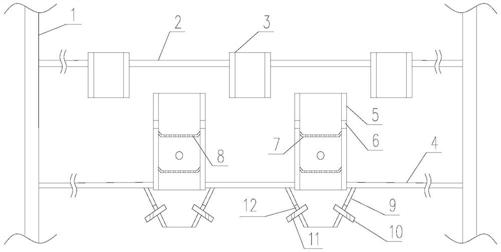
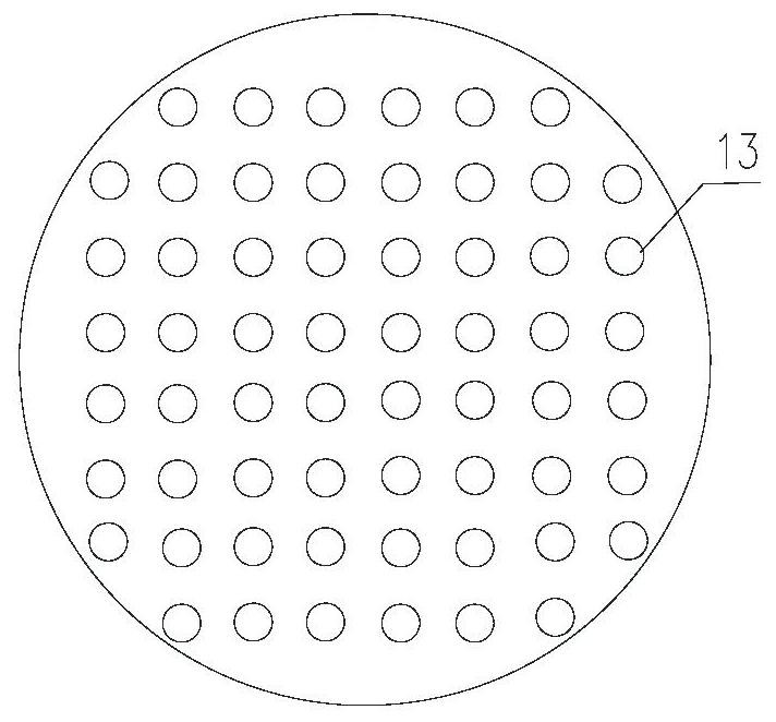
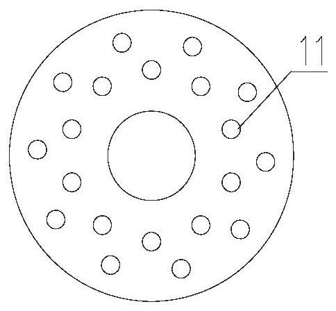
[0043] Such as Figure 1~3 As shown, the gas-liquid distribution device provided by the present invention comprises a reactor wall 1 and a distribution plate 2 arranged from top to bottom along the reactor wall, a guide pipe 3, an overflow pipe 5, a distribution plate 4, fixed on the distribution plate Disperser arranged under the plate 4 and coaxial with the overflow pipe 5; the distribution plate 2 is a flat plate, the shape is consistent with the cross-sectional shape of the reactor, supported on the reactor wall 1, and a circular diversion hole 13 is opened on the plate to guide The orifices 13 are arranged in a square manner; the diversion pipe 3 is installed in the diversion hole 13, the shape of the diversion pipe is consistent with the diversion hole, and the upper and lower ends of the diversion pipe protrude from the upper and lower surfaces of the distribution plate 1; the overflow pipe 5 is two A round tube with an open end, the lower end of which is fixed on the i...


PUM


Abstract

The invention discloses a gas-liquid distribution device. The gas-liquid distribution device comprises a reactor wall, and a distribution plate, an overflow pipe and a distribution disc which are arranged along the reactor wall from top to bottom, wherein the distribution plate is a flat plate, is consistent with the section of a reactor in shape, is supported on the wall of the reactor and is provided with flow guide holes; the overflow pipe is a circular pipe with two open ends, the lower end of the overflow pipe is fixed on a mounting hole in the distribution disc, and overflow holes are uniformly formed in the pipe wall along the circumferential direction to serve as liquid phase channels; and the upper end of the overflow pipe is a free end, is positioned below the distribution plate, is over against the center of a non-perforated area between the flow guide holes in the distribution plate and is completely shielded by the non-perforated area. Compared with a common scheme of blocking overflow pipes one by one in the prior art, the distribution plate used in the invention has the advantages of small processing amount, short manufacturing period and low cost while the purpose of preventing an upper liquid phase from directly entering the overflow pipes can also be achieved. According to the invention, the contact time of a gas phase and a liquid phase is prolonged, dissolution of the gas phase in the liquid phase is promoted, and meanwhile, the phenomenon of inner wall flow of the overflow pipe is effectively avoided.

Description

technical field [0001] The invention belongs to the field of petroleum refining and chemical equipment, and relates to a reactor internal component, in particular to a gas-liquid distribution device. Background technique [0002] In recent years, with the gradual upgrading of petrochemical product quality standards and increasingly stringent environmental protection regulations, hydrogenation technology has played an increasingly important role in the oil refining industry. In order to improve economic efficiency and meet the requirements of environmental protection, oil refining enterprises have rapidly expanded the hydrotreating capacity of various oil products. [0003] The key core equipment for hydroprocessing is the hydrogenation reactor. Inside the hydrogenation reactor, a mixture of a certain proportion of hydrogen (gas phase) and raw oil (liquid phase) is used at a certain temperature and pressure to complete various hydrogenation processes. hydrogen reaction. The...

Claims


Application Information

Patent Timeline
IPC IPC(8): B01J8/00
CPCB01J8/008
Inventor 邓矛晁君瑞
Owner CHINA PETROLEUM & CHEM CORP
Why Eureka
Try Eureka