Shearing device of shear wall pulling piece and using method

A shearing device and shear wall technology, applied in the field preparation of building components, machine tools suitable for grinding workpiece edges, formwork/formwork/working frame connectors, etc., can solve laborious and stabbing construction workers And other issues

Inactive Publication Date: 2021-07-06
中建新疆建工集团第五建筑工程有限公司
View PDF14 Cites 0 Cited by
  • Summary
  • Abstract
  • Description
  • Claims
  • Application Information

AI Technical Summary

Problems solved by technology

[0004] However, in the specific implementation of the above-mentioned patents, the device needs to be operated by the user with a hand-held device. It is laborious to deal with a large amount of breaking work, and the breaking point is relatively sharp, and the broken pull pieces scattered on the ground may also stab construction workers. risks of

Method used


Image

  • Shearing device of shear wall pulling piece and using method
  • Shearing device of shear wall pulling piece and using method
  • Shearing device of shear wall pulling piece and using method

Examples


Embodiment 1

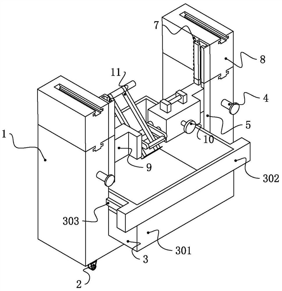
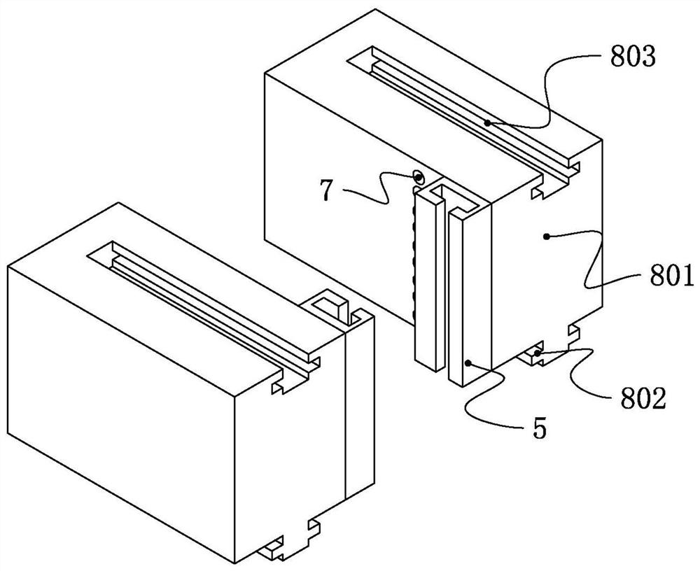
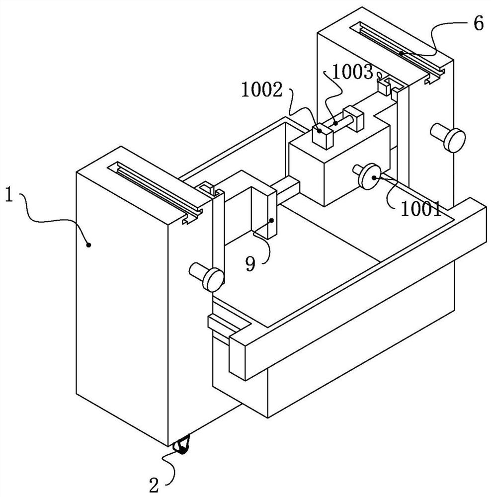
[0018] Embodiment 1, as figure 1 , figure 2 , image 3 , Figure 4 , Figure 5 , Figure 6 and Figure 7 As shown, a shearing device for a shear wall pull piece includes a U-shaped main body 1, universal wheels 2 are fixedly installed at the four corners of the bottom end of the U-shaped main body 1, and the bottom end of the U-shaped mouth of the U-shaped main body 1 is snapped and installed There is a collection mechanism 3, two pressing columns 4 are fixedly installed on the front of the U-shaped main body 1, vertical chute 5 is fixedly installed on the side of the inner wall of the U-shaped main body 1, and a sliding mechanism is engaged and connected between the vertical chute 5 9. The sliding mechanism 9 is provided with a grinding mechanism 10 and a cutting mechanism 11. The two top ends of the U-shaped main body 1 are provided with first transverse grooves 6, and the inner wall of the U-shaped main body 1 is provided on one side of the vertical chute 5. There ar...

Embodiment 2

[0024] Embodiment 2. A method for using a shear wall pull-tab shearing device, comprising the following steps: a. installation of template pull-tab components; b. installation of back corrugated diagonal bracing components; c.

[0025] Among them, the installation of template puller components: upload the templates that have been dismantled and cleaned in the lower layer according to the area and order and place them securely. If stacked, they should be facing upwards, so that the release agent can be applied, and then removed one by one. Molding agent, when the interior wall formwork is installed, it starts from the inner corner (corner) and extends to both sides according to the order of the formwork number. In order to prevent the formwork from falling, temporary fixed diagonal braces (wood, steel pipes, etc.) Apply a suitable release agent to each template, rotate the C slot vertically by 45°, snap it into one side of the pull tab, then rotate it in the opposite direction b...


PUM


Abstract

The invention discloses a shearing device of a shear wall pulling piece and a using method. The shearing device comprises a U-shaped main body; universal wheels are fixedly installed at the four corners of the bottom end of the U-shaped main body; a collecting mechanism is installed at the bottom end of a U-shaped opening of the U-shaped main body in a clamped mode; two pressing columns are fixedly installed on the front face of the U-shaped main body; vertical sliding grooves are fixedly formed in the edge sides of the inner wall of the U-shaped main body; a sliding mechanism is connected between the vertical sliding grooves in a clamped mode; and a polishing mechanism and a cutting mechanism are arranged on the sliding mechanism. According to the shearing device, through the cutting mechanism on the sliding mechanism, the rapid cutting of the pulling piece on the surface of a wall is achieved, and the problem that in the prior art, a hammer or other tools need to be used for smashing a pulling piece to be flat or smashing the pulling piece out, and the process is strenuous is solved; and through the polishing mechanism on the sliding mechanism, the cut pulling piece is polished, and the problem that in the prior art, the follow-up construction is affected due to the fact that the end opening treatment of the pulling piece is not good enough is solved.

Description

technical field [0001] The invention relates to the technical field of building construction, in particular to a shearing device and a using method of a shear wall pull piece. Background technique [0002] According to the Chinese utility model (application number: CN202010966641.8) disclosed "a steel plate composite wall pull bolt assembly device and its assembly method", it includes a pull bolt positioning device and a single corrugated steel plate positioning device, a pull bolt positioning device It is used to limit the tension bolt, and the single corrugated steel plate positioning device is used to limit the single corrugated steel plate; through the single corrugated steel plate positioning device, it moves to the direction of the tension bolt positioning device, and the single corrugated steel plate is installed on the tension bolt . The method includes: a. installing the tension bolts on the tension bolt positioning device; b. pressing the tension bolts with the cl...

Claims


Application Information

Patent Timeline
Patent Type & Authority Applications(China)
IPC IPC(8): B23P23/04B24B9/04B23Q7/10E04G11/06E04G17/00
CPCB23P23/04B24B9/04B23Q7/10E04G11/06E04G17/00
Inventor 刘俊璞石风生姜胜利许素环刘俊鹏杨怀佳李志刚刘凤涛樊旭强杨硕谭志强
Owner 中建新疆建工集团第五建筑工程有限公司
Why Eureka
Try Eureka