
Glass edge grinding device capable of collecting waste residues and implementation method thereof

A glass edging and glass technology, which is applied to grinding drive devices, grinding/polishing safety devices, grinding machines, etc., can solve the problems of low glass edging efficiency, increased operator workload, waste collection and other problems

Inactive Publication Date: 2021-07-06
安徽晶晶玻璃制品有限公司
View PDF8 Cites 1 Cited by
  • Summary
  • Abstract
  • Description
  • Claims
  • Application Information

AI Technical Summary

Problems solved by technology

[0003] After the glass is cut, burrs will be generated on the side of the glass. Therefore, it is necessary to grind the side of the glass to meet the production requirements. In the existing glass edging method, there is a situation where the operator manually performs the glass edging. This kind of glass The edging method increases the workload of the operator, which makes the glass edging efficiency low and cannot effectively collect the waste generated by glass edging

Method used


Image

  • Glass edge grinding device capable of collecting waste residues and implementation method thereof
  • Glass edge grinding device capable of collecting waste residues and implementation method thereof
  • Glass edge grinding device capable of collecting waste residues and implementation method thereof

Examples


Embodiment approach

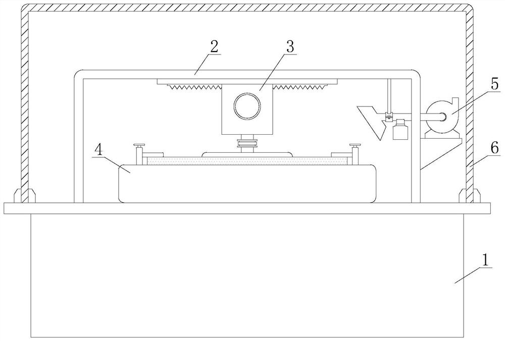
[0036] In order to better demonstrate the implementation process of the glass edging device that can collect waste slag, this embodiment now proposes an implementation method of a glass edging device that can collect waste slag, including the following steps:

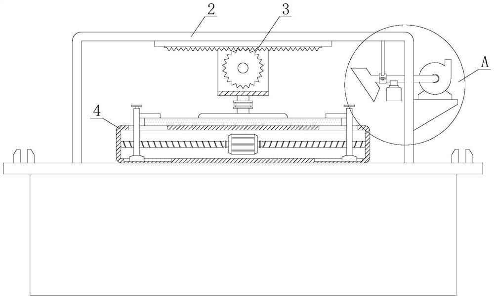
[0037] S1: The glass is placed on the clamping base 41 and the side of the glass is close to the glass edging block 312. The double-axis motor 42 drives the first driving screw 43 and the second driving screw 44 to rotate, so that the adjacent guide slides Seat 451 moves toward each other;

[0038] S2: The hand wheel 4521 drives the third transmission screw 452 to rotate, so that the clamping platen 454 descends on the bar-shaped guide column 453, and the glass is pressed on the clamping base 41 through the clamping platen 454;

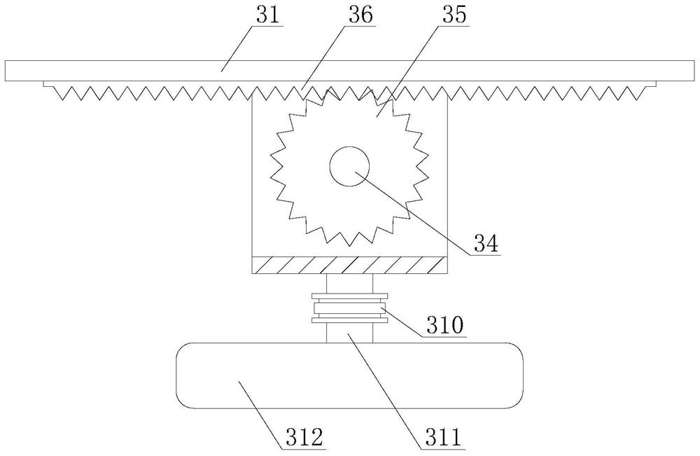
[0039] S3: The driving motor 33 drives the first rotating shaft 34 and the transmission gear 35 to rotate, so that the traversing edging slide 32 moves on the fixed base 31, and the glass is ed...


PUM


Abstract

The invention discloses a glass edging device capable of collecting waste residues and an implementation method of the glass edging device, and belongs to the technical field of glass edging. The glass edging device comprises a machining table, wherein a fixing support is installed on the machining table, a glass edging mechanism is arranged on the fixing support, and a glass clamping mechanism is arranged below the glass edging mechanism; a glass waste residue collecting mechanism is further installed on the side surface of the fixing support and faces towards the polished glass edge, and the machining table is further covered with a transparent blocking cover. According to the glass edge grinding device capable of collecting the waste residues and the implementation method of the glass edge grinding device disclosed by the invention, glass is subjected to edge grinding through the rotating and transversely-moving glass edge grinding block, so that the workload of operators can be relieved, and the glass edge grinding efficiency is high; in the glass edge grinding process, a draught fan is started to generate negative pressure, a collecting cover sucks the glass waste residues and enables the glass waste residues to enter a residue collecting tube, and therefore, the glass edge grinding efficiency is improved. As the glass waste residues cannot pass through a filter screen and fall into a residue collecting box under the blocking effect of the filter screen, the glass waste residues are collected through the residue collecting box, and manual cleaning is not needed.

Description

technical field [0001] The invention relates to the technical field of glass edging, in particular to a glass edging device capable of collecting waste slag and an implementation method thereof. Background technique [0002] Glass is an amorphous inorganic non-metallic material, generally made of various inorganic minerals (such as quartz sand, borax, boric acid, barite, barium carbonate, limestone, feldspar, soda ash, etc.) of. Its main components are silicon dioxide and other oxides, which are widely used in buildings, used for wind and light transmission, and belong to a mixture. There are also colored glass that is mixed with certain metal oxides or salts to show color. And tempered glass made by physical or chemical methods. Sometimes some transparent plastics (such as polymethyl methacrylate) are also called plexiglass. [0003] After the glass is cut, burrs will be generated on the side of the glass. Therefore, it is necessary to grind the side of the glass to meet...

Claims


Application Information

Patent Timeline
IPC IPC(8): B24B9/08B24B41/04B24B41/06B24B47/20B24B47/22B24B55/04B24B55/06B24B55/12
CPCB24B9/08B24B41/06B24B47/22B24B41/04B24B47/20B24B55/04B24B55/06B24B55/12
Inventor 倪明发圣绍杰倪菊花粱永旗万银兵
Owner 安徽晶晶玻璃制品有限公司
Learn More