Injection head and injection mechanism of injection molding machine

A spray mechanism and spray head technology, applied in the field of spray heads and spray mechanisms, can solve problems such as easy blockage of spray heads, influence of maintenance efficiency, waste of raw materials, etc.

Inactive Publication Date: 2021-07-06
柏松
View PDF1 Cites 1 Cited by
  • Summary
  • Abstract
  • Description
  • Claims
  • Application Information

AI Technical Summary

Problems solved by technology

[0003] The publication number is CN207172603U, which provides a nozzle for injection molding machine, which realizes the quick installation and quick disassembly of the nozzle and the nozzle through the connecting piece, the spring and the through groove, so as to facilitate the cleaning and maintenance of the nozzle. Although the ease of use of the nozzle has been improved, the following deficiencies still exist in the actual use process: 1. After the injection is completed, it is difficult for the injection mechanism to stop the injection of the raw material in an instant, so there is still a certain gap after the injection of the nozzle is completed. The raw material will be supplied to the nozzle, causing the nozzle to inject some melted raw material from the nozzle after the nozzle is injected into the mold, which will not only waste raw material, but also easily cause the nozzle to be blocked; 2. The existing injection molding machine sprays The head is not equipped with a heating and cooling device. When the melted raw material passes through the nozzle, it is very easy to harden and block the nozzle, which will affect the effect of injection molding. In addition, the nozzle cannot be cooled quickly during maintenance, which affects the efficiency of maintenance.

Method used


Image

  • Injection head and injection mechanism of injection molding machine
  • Injection head and injection mechanism of injection molding machine
  • Injection head and injection mechanism of injection molding machine

Examples


Embodiment

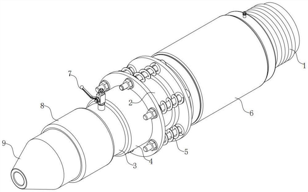
[0029] see Figure 1 to Figure 6 , the present invention provides a technical solution:

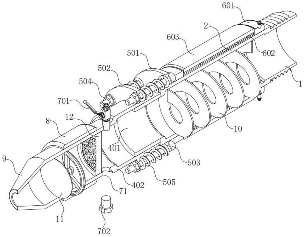
[0030] An injection head of an injection molding machine, comprising a mounting pipe 1, a first feeding pipe 2, a second feeding pipe 3, a buffer pipe assembly 4, a buffer reset mechanism 5, a heating and cooling assembly 6, a cleaning assembly 7, a threaded pipe 8 and Injection nozzle 9, wherein:

[0031] The interior of the installation pipe 1, the first feed pipe 2, the second feed pipe 3, the buffer pipe assembly 4 and the injection nozzle 9 are connected, and one end of the installation pipe 1 is connected to the first feed pipe 2, and the second The other end of a feed pipe 1 is connected with the buffer pipe assembly 4, the other end of the buffer pipe assembly 4 is connected with the second feed pipe 3, and the buffer reset mechanism 5 is installed on the buffer pipe assembly 4, so The size of the internal volume of the buffer tube assembly 4 can be adjusted under the control of...


PUM


Abstract

The invention provides an injection head and an injection mechanism of an injection molding machine. The injection head comprises a mounting pipe, a first feeding pipe, a second feeding pipe, a buffer pipe assembly, a buffer reset mechanism, a heating and cooling assembly, a cleaning assembly, a threaded pipe and an injection nozzle. During injection molding, a buffer pipe moves forward, the size of the buffer pipe assembly is reduced, after injection molding is finished, a reset spring drives the buffer pipe to reset, so that the internal volume of the buffer pipe assembly is enlarged, a small amount of raw materials are temporarily stored, the raw materials are prevented from still flowing out of the injection nozzle after injection is completed, and the phenomenon that the raw materials flowing out of the injection nozzle are solidified and block the injection nozzle can be effectively prevented, and when heating is needed, a heating wire is used for heating the injection head through the electromagnetic induction principle, a vapor chamber plays a good role in soaking so as to quickly heat the injection head, circulating cooling water is introduced into a heat dissipation water tank during maintenance, and at the moment, the vapor chamber can quickly take away heat on the surface of the injection head so as to quickly cool the injection head.

Description

technical field [0001] The invention relates to the technical field of injection molding machine equipment, in particular to an injection head of an injection molding machine and an injection mechanism thereof. Background technique [0002] Now in our country, the demand for injection molding products is increasing day by day, the scope of use of injection molding products is also expanding, and the application of injection molding machines is becoming more and more extensive. Injection molding machines are the main molding equipment for making plastic products of various shapes using plastic molding molds. It is vertical, horizontal, and all-electric. The injection molding machine can heat the plastic and apply high pressure to the molten plastic to make it shoot out and fill the mold cavity. It mainly sprays the raw materials through the injection head, which mainly injects the The raw material processing unit and the mold are connected to the workpiece, while ensuring the...

Claims


Application Information

Patent Timeline
Patent Type & Authority Applications(China)
IPC IPC(8): B29C45/20B29C45/74
CPCB29C45/20B29C45/74
Inventor 柏松
Owner 柏松
Why Eureka
Try Eureka