Diffuser, air supply device and dust collector

A technology of diffusers and stationary vanes, which is applied in the direction of vacuum cleaners, pump devices, components of pumping devices for elastic fluids, etc., and can solve the problems of large airflow loss and other problems

Active Publication Date: 2021-07-06
GUANGDONG WELLING ELECTRIC MACHINE MFG
View PDF7 Cites 0 Cited by
  • Summary
  • Abstract
  • Description
  • Claims
  • Application Information

AI Technical Summary

Problems solved by technology

[0003] The purpose of the embodiment of the present application is to provide a diffuser, aiming to solve the technical problem of large flow loss of the air flow when passing through the diffuser in the prior art

Method used


Image

  • Diffuser, air supply device and dust collector
  • Diffuser, air supply device and dust collector
  • Diffuser, air supply device and dust collector

Examples


Embodiment Construction

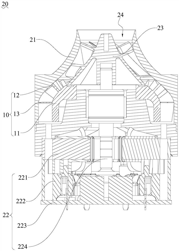
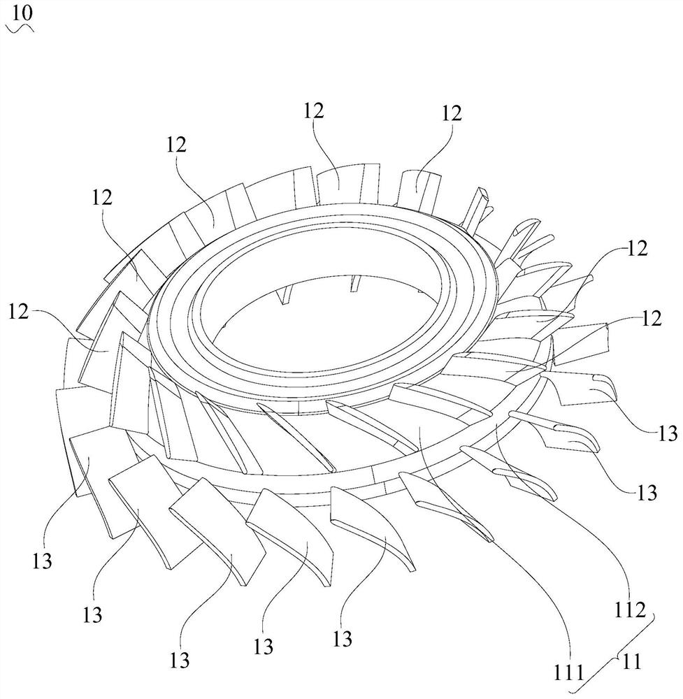
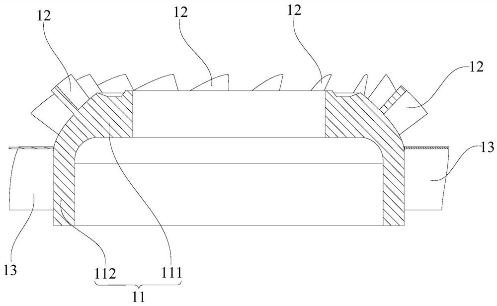
[0036] Embodiments of the present application are described in detail below, examples of which are shown in the drawings, wherein the same or similar reference numerals denote the same or similar elements or elements having the same or similar functions throughout. Attached below by reference Figure 1-6 The described embodiments are exemplary and are intended to explain the application and not to be construed as limiting the application.

[0037] In the description of the present application, it should be understood that the terms "length", "width", "upper", "lower", "front", "rear", "left", "right", "vertical", The orientation or positional relationship indicated by "horizontal", "top", "bottom", "inner", "outer", etc. are based on the orientation or positional relationship shown in the drawings, and are only for the convenience of describing the application and simplifying the description, rather than Nothing to indicate or imply that a referenced device or element must ha...


PUM


Abstract

The invention belongs to the technical field of cleaning equipment, and particularly relates to a diffuser, an air supply device and a dust collector. The diffuser comprises a base, a first row of stationary blades and a second row of stationary blades, the base comprises a cylindrical part and a circular truncated cone part, the circular truncated cone part is provided with a large opening end and a small opening end, and the large opening end is in butt joint with the axial end of the cylindrical part; and the first row of stationary blades are arranged on the outer ring wall of the circular truncated cone part and distributed in the circumferential direction of the circular truncated cone part, and the second row of stationary blades are arranged on the outer ring wall of the cylindrical part and distributed in the circumferential direction of the cylindrical part. The configuration of the circular truncated cone part enables the contour molded line of the base to meet good fitting of the airflow flowing direction, the airflow flowing smoothness is improved, the flowing separation phenomenon formed near the outer ring wall of the circular truncated cone part or the cylindrical part when airflow flows through the first row of stationary blades and the second row of stationary blades is remarkably reduced, therefore, the flow loss of the airflow flowing through the diffuser is effectively reduced, and the performance of the diffuser for decelerating and pressurizing the airflow is improved.

Description

technical field [0001] The application belongs to the technical field of cleaning equipment, and in particular relates to a diffuser, an air supply device and a vacuum cleaner. Background technique [0002] An air supply device is usually provided in the vacuum cleaner, and a diffuser is provided in the air supply device to convert the kinetic energy of the airflow passing through the air supply device into pressure energy, thereby reducing the flow loss of the airflow. The diffuser is usually equipped with stator blades to guide and pressurize the airflow. However, the existing diffuser still cannot fully realize the conversion between the kinetic energy and the pressure energy of the airflow passing through the diffuser, which will cause a large flow loss when the airflow flows through the diffuser. Contents of the invention [0003] The purpose of the embodiments of the present application is to provide a diffuser, aiming at solving the technical problem in the prior a...

Claims


Application Information

Patent Timeline
IPC IPC(8): F04D29/44F04D29/66F04D25/08A47L5/22
CPCF04D29/444F04D29/667F04D25/08A47L5/22
Inventor 张伟周亚运蒋婷婷杨帆吕琢李虎
Owner GUANGDONG WELLING ELECTRIC MACHINE MFG
Why Eureka
Try Eureka