
Hydraulic oil dewatering system and method for side thruster

A technology of hydraulic system and hydraulic oil, applied in the field of hydraulic oil dewatering system of thruster, can solve the problems of emulsification of lubricating oil, shortening service life, mixing of sea water and so on

Active Publication Date: 2021-07-06
GUANGZHOU WENCHONG SHIPYARD CO LTD
View PDF6 Cites 0 Cited by
  • Summary
  • Abstract
  • Description
  • Claims
  • Application Information

AI Technical Summary

Problems solved by technology

[0003] Since the sealing device used in the rotary position of the shaft propeller of the ship's thruster is usually a lip-shaped radial seal, during the ship's navigation, due to the harsh environment or damage to the lip seal, seawater will be mixed into the hydraulic system of the side thruster , and even lead to emulsification of the lubricating oil, the water ingress of the hydraulic oil has a great impact on the normal use of the hydraulic system of the ship's side thruster, shortening the service life
At present, there is no effective technical solution for the hydraulic oil removal of ship side thrusters

Method used


Image

  • Hydraulic oil dewatering system and method for side thruster

Examples


Embodiment Construction

[0034] Embodiments of the present invention will be described in detail below, and examples of the embodiments are shown in the drawings, wherein the same or similar reference numerals denote the same or similar components or components having the same or similar functions throughout. The embodiments described below by referring to the figures are exemplary and are intended to explain the present invention and should not be construed as limiting the present invention.

[0035] In the description of the present invention, unless otherwise clearly stipulated and limited, the terms "connected", "connected" and "installed" should be understood in a broad sense, for example, it can be an installation connection, a detachable connection, or a mechanical connection. A connection can also be an electrical connection, a direct connection, or an indirect connection through an intermediary, or an internal connection between two elements or an interaction relationship between two elements....


PUM


Abstract

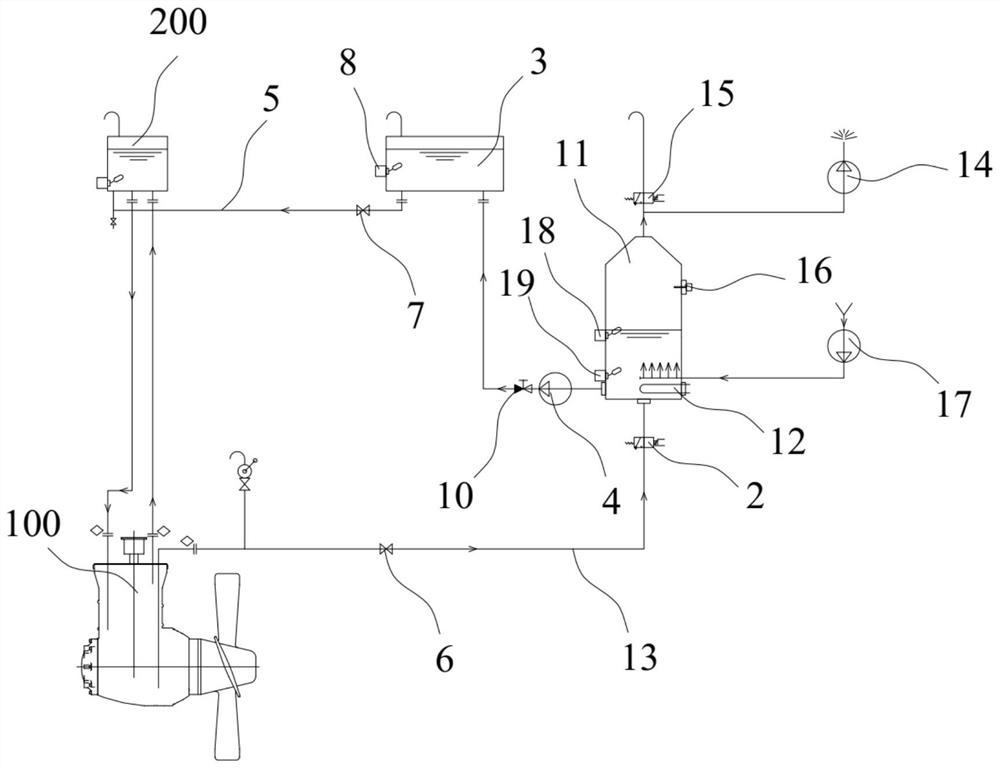
The invention belongs to the technical field of hydraulic oil dewatering, and discloses a hydraulic oil dewatering system and method for a side thruster. The dewatering system comprises a dewatering assembly, a first valve body, a buffer cabinet, a conveying pump and an oil return pipe; the dewatering assembly comprises a treatment cabinet, a heater, a liquid inlet pipe and a water outlet pipe; the heater is arranged in the treatment cabinet and used for heating hydraulic oil in the treatment cabinet; the treatment cabinet is communicated with the side thruster through the liquid inlet pipe, and the position height of an gravity oil cabinet for supplying oil to the side thruster is higher than that of the treatment cabinet; the first valve body is arranged on the liquid inlet pipe; the treatment cabinet is communicated with the buffer cabinet through the water outlet pipe; the conveying pump is arranged on the water outlet pipe; and the buffer cabinet is communicated with the gravity oil cabinet through the oil return pipe, and the position height of the gravity oil cabinet is the same as that of the buffer cabinet. The hydraulic oil dewatering system and method for the side thruster provided by the invention can effectively dewater from the hydraulic oil, and can be selected to operate in the working state of the side thruster, so that normal work of a hydraulic system is not influenced.

Description

technical field [0001] The invention belongs to the technical field of hydraulic oil water removal, and in particular relates to a side thruster hydraulic oil water removal system and method. Background technique [0002] The ship side thruster is a device to help the ship turn, which can improve the maneuverability of the ship, mainly to meet the needs of low-speed navigation and maneuvering from the dock. It is generally installed in the transverse pipe at the bow of the ship, and the fixed propeller or adjustable propeller system driven by the motor is often used, which can discharge the water from one side to the other side, and use the reaction force of the water to help the ship turn. Both fixed propeller and controllable propeller systems of side thrusters have hydraulic oil systems. [0003] Since the sealing device used in the rotation position of the shaft propeller of the ship's thruster is usually a lip-shaped radial seal, during the ship's navigation, due to th...

Claims


Application Information

Patent Timeline
Patent Type & Authority Applications(China)
IPC IPC(8): F15B21/041F15B21/0423F15B21/0427F15B19/00
CPCF15B21/041F15B21/0423F15B21/0427F15B19/00
Inventor 何超平吴兴武陆佳潘东徐劲张勇胡登峰张俊江许炜麟
Owner GUANGZHOU WENCHONG SHIPYARD CO LTD
Learn More