
Plastic film water removal device and method

A plastic film and moisture technology, which is applied in the direction of drying solid materials, drying gas arrangement, and drying solid materials without heating, etc., can solve the problems of strong limitations, inability to reuse, poor water removal effect, etc., and achieve wide application range, Strong practicability and good water removal effect

Active Publication Date: 2021-10-26
广州中创建筑科技有限公司
View PDF7 Cites 0 Cited by
  • Summary
  • Abstract
  • Description
  • Claims
  • Application Information

AI Technical Summary

Problems solved by technology

[0002] The flat wire is formed by the wire drawing machine by heating, extruding, cutting, stretching and winding the raw material. After the raw material is extruded, it is formed into a plastic film in the pool. In the plastic flat wire drawing production process, the plastic film after the water bath It also contains a large amount of water, which needs to be dried before entering the subsequent processing technology. The existing plastic film water removal device uses two scrapers to remove water from the plastic film, and the two scrapers are respectively set on the plastic film. The water removal effect is poor at the upper and lower surfaces; and the existing plastic film water removal devices cannot remove water from plastic films of different widths and thicknesses, which has strong limitations and cannot be widely used; the existing plastic film water removal devices Generally, the absorbent cotton of the device cannot be reused after absorbing the moisture on the surface of the plastic film, and the absorbent cotton needs to be replaced, which is very time-consuming and laborious

Method used


Image

  • Plastic film water removal device and method
  • Plastic film water removal device and method
  • Plastic film water removal device and method

Examples


Embodiment Construction

[0035] The following will clearly and completely describe the technical solutions in the embodiments of the present invention with reference to the accompanying drawings in the embodiments of the present invention. Obviously, the described embodiments are only some, not all, embodiments of the present invention. All other embodiments obtained by persons of ordinary skill in the art based on the embodiments of the present invention belong to the protection scope of the present invention.

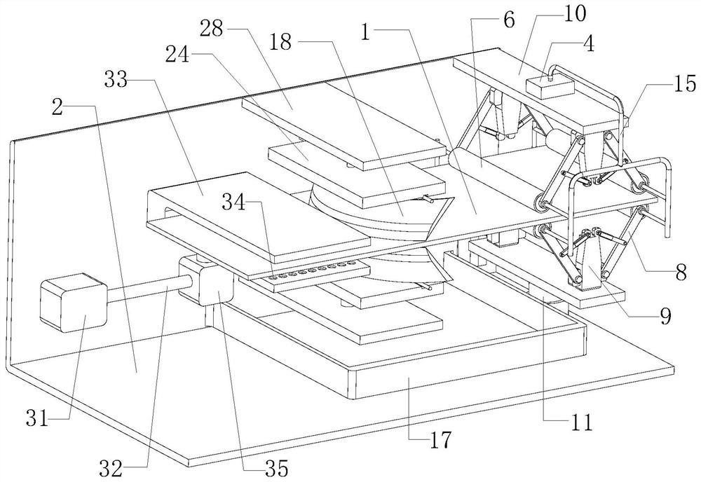
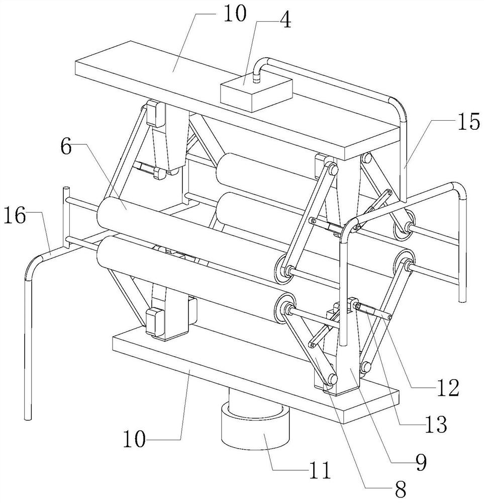
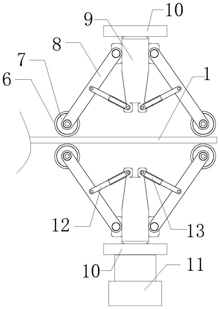
[0036] See attached Figure 1-11 As shown, a plastic film dewatering device includes a guide roller group, a wiper blade group and a drying unit through which the plastic film 1 passes sequentially. The guide roller group is used to guide and compress the plastic film 1, and the wiper blade group is used to For extruding and scraping the surface of the plastic film 1 to remove moisture, the drying unit is used to dry the plastic film 1. The guide roller group, the wiper board group and the dr...


PUM


Abstract

The invention discloses a plastic film water removal device and method. The device comprises a guide roller set, a water scraping plate set and a drying unit, a plastic film passes through the guide roller set, the water scraping plate set and the drying unit in sequence, the guide roller set, the water scraping plate set and the drying unit are fixedly connected to a rack and electrically connected with a numerical control unit, the guide roller set presses and guides the upper surface and the lower surface of the conveyed plastic film under the control of the numerical control unit, a vacuum cavity communicating with a vacuum pump is formed in the guide roller set, the vacuum pump is electrically connected with the numerical control unit, a plurality of adsorption holes communicating with the vacuum cavity are formed in the guide roller set at intervals in a penetrating mode, and the surface of the guide roller set is coated with a water absorption sponge layer. A width adjusting unit used for adjusting the width of the water scraping plate set is arranged on the water scraping plate set, and the numerical control unit controls the width adjusting unit to adjust the width of the water scraping plate set so as to effectively remove water from plastic films with different widths.

Description

technical field [0001] The invention relates to the technical field of plastic film water removal, in particular to a plastic film water removal device and method. Background technique [0002] The flat wire is formed by the wire drawing machine by heating, extruding, cutting, stretching and winding the raw material. After the raw material is extruded, it is formed into a plastic film in the pool. In the plastic flat wire drawing production process, the plastic film after the water bath It also contains a large amount of water, which needs to be dried before entering the subsequent processing technology. The existing plastic film water removal device uses two scrapers to remove water from the plastic film, and the two scrapers are respectively set on the plastic film. The water removal effect is poor at the upper and lower surfaces; and the existing plastic film water removal devices cannot remove water from plastic films of different widths and thicknesses, which has strong...

Claims


Application Information

Patent Timeline
IPC IPC(8): F26B5/16F26B13/04F26B13/14F26B21/00F26B25/04
CPCF26B5/16F26B13/001F26B13/14F26B21/001F26B21/004F26B25/04
Inventor 胡勇强
Owner 广州中创建筑科技有限公司
Learn More