Drain apparatus

A technology of drainage mechanism and strip plate, applied in furnaces, heat treatment equipment, coating of superimposed layers, etc., can solve the problems of strip steel oxidation, refrigerant flowing downward, and insufficient water removal, and achieve the effect of reducing water removal load.

Active Publication Date: 2009-12-16
PRIMETALS TECHNOLOGIES JAPAN LTD
View PDF1 Cites 0 Cited by
  • Summary
  • Abstract
  • Description
  • Claims
  • Application Information

AI Technical Summary

Problems solved by technology

[0007] However, when the above-mentioned conventional dewatering device is used in the production of the above-mentioned special steel plate, since the gas is injected to the upstream side (upper side) of the strip conveying direction, when the injection amount and injection pressure of the gas are increased in order to improve the dewatering performance , it is possible that the downstream side (lower side) becomes negative pressure and causes oxidation of the strip, etc.
In addition, in order to avoid such a problem, the gas is also injected downstream in the strip conveying direction, but the liquid refrigerant that cannot be removed by injecting gas on the upstream side may flow downward more seriously, and water removal may not be sufficient.

Method used


Image

  • Drain apparatus
  • Drain apparatus
  • Drain apparatus

Examples


Embodiment Construction

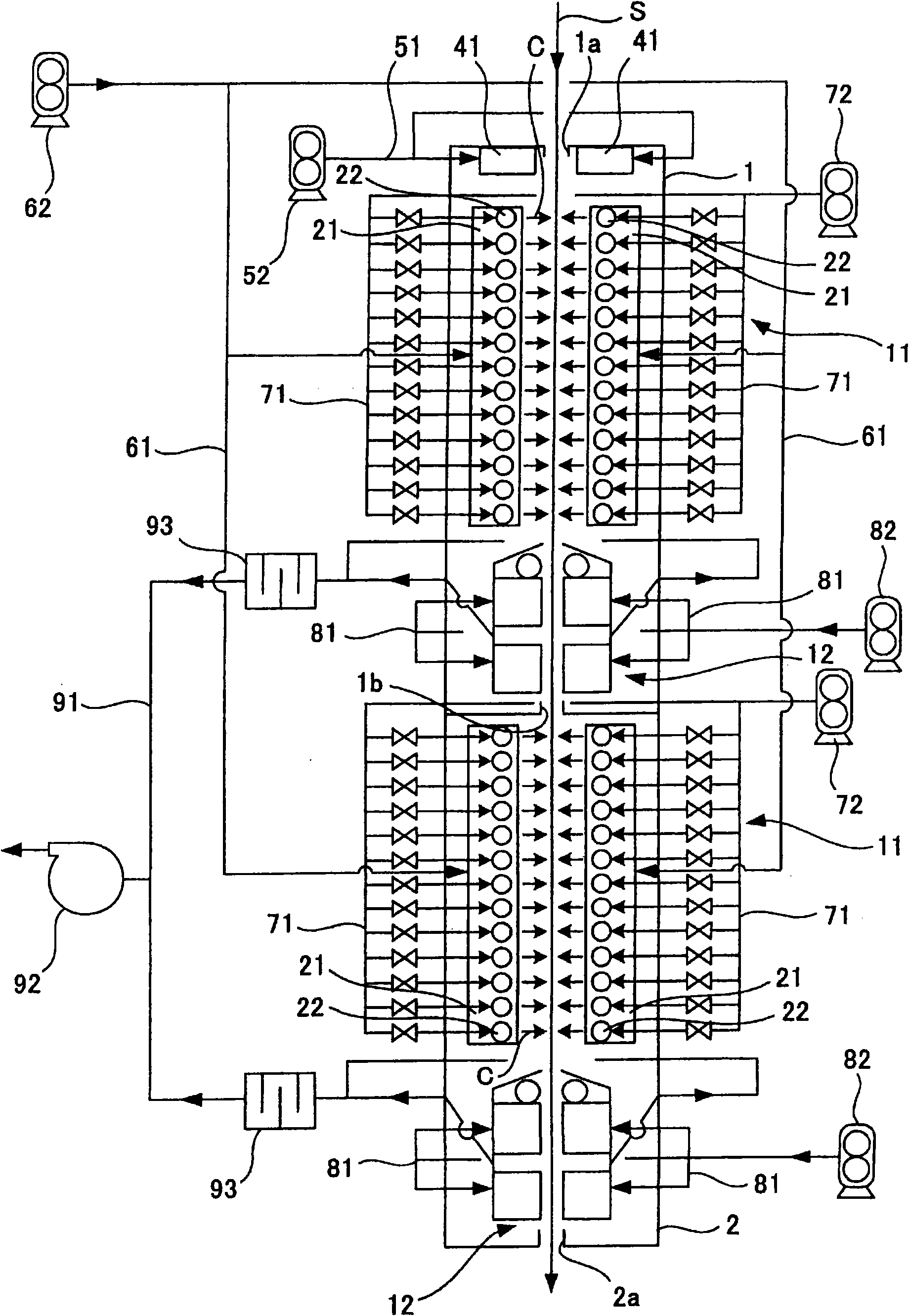
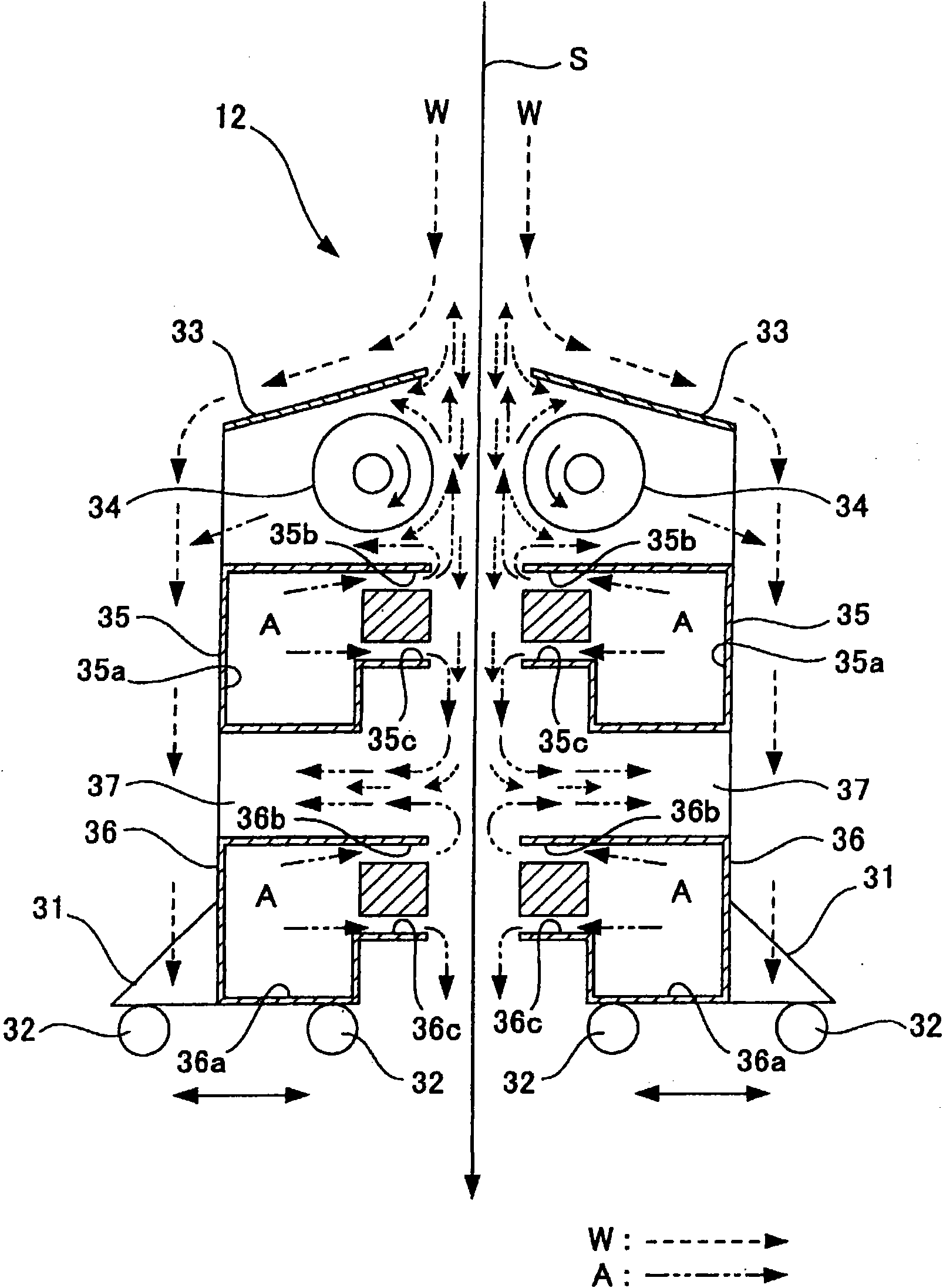
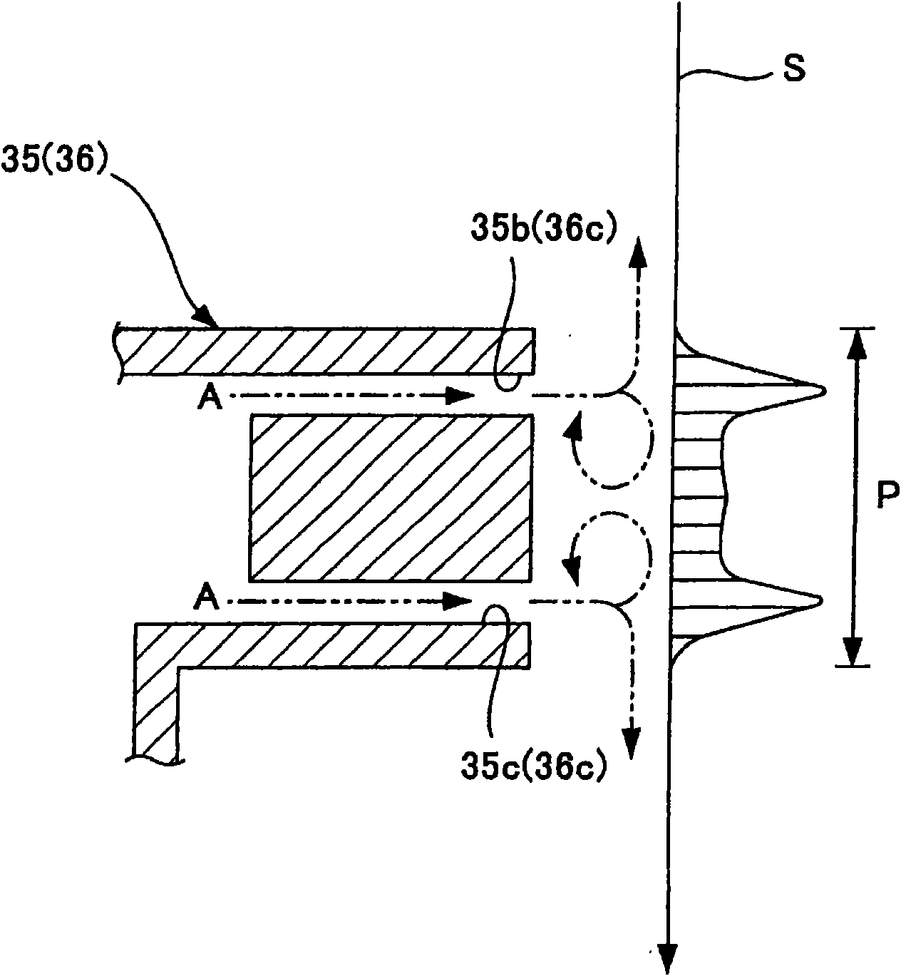
[0022] Next, the dewatering device according to the present invention will be described in detail with reference to the drawings. In addition, this embodiment is an embodiment in which the water removal device according to the present invention is applied to a cooling zone of a continuous annealing facility. figure 1 It is a schematic diagram of a cooling zone of a continuous annealing facility equipped with a water removal device according to an embodiment of the present invention. figure 2 It is a schematic cross-sectional view of the dewatering device according to one embodiment of the present invention. image 3 It is a graph showing the pressure distribution of the steel strip by the air injected by the upper and lower slits of the nozzle.

[0023] Such as figure 1 As shown, in the unshown continuous annealing facility for heat-treating the steel strip S, the primary cooling zone 1 and the secondary cooling zone 2 for cooling the steel strip S are arranged adjacently u...


PUM


Abstract

A drain apparatus that is capable of draining a large volume of liquid cooling medium flowing downward along a strip steel. The drain apparatus is one comprising paired upper nozzles (35) and lower nozzles (36) disposed opposite to each other so as to have strip steel (S) interposed therebetween on the exit side of primary cooling zone (1) and secondary cooling zone (2) for cooling vertically conveyed heated strip steel (S) with the use of steam water (C), wherein on the planes of the upper nozzles (35) and lower nozzles (36) opposite to the strip steel (S), superior slits (35b,36b) and inferior slits (35c,36c) for drain of cooling water (W) flowing downward along the strip steel (S) by jetting of air (A), furnished with openings approximately perpendicular to the direction of conveyance of the strip steel (S) are provided along the direction of conveyance of the strip steel (S).

Description

technical field [0001] The present invention relates to a dewatering device for removing the refrigerant flowing downward along the strip by injecting gas into the strip after cooling Background technique [0002] Generally, a steel strip production line is equipped with various equipment such as a rolling facility, a continuous annealing facility, and a continuous plating facility, and the strip is sequentially fed to these facilities to manufacture a steel plate. During rolling, annealing, and electroplating, the conveyed steel strip is heated at a high temperature, so a cooling device for cooling the heated strip is provided on the downstream side of the strip conveying direction of the above-mentioned equipment. The cooling device cools the steel strip by spraying a refrigerant such as a liquid or a gas-liquid mixture of a liquid and a gas on the conveyed steel strip. [0003] However, in the case where the cooling device is of the vertical type, that is, in the case of...

Claims


Application Information

Patent Timeline
Patent Type & Authority Applications(China)
IPC IPC(8): C21D9/52C21D9/573
CPCC21D9/52C23C28/023C23C2/40C23C2/26C21D9/573C23C2/003C23C2/0038
Inventor 藤冈宏规吉川雅司
Owner PRIMETALS TECHNOLOGIES JAPAN LTD
Why Eureka
Try Eureka