
Head-swinging dual-compound braking device

A compound braking and driving device technology, applied in the direction of brake types, axial brakes, brake actuators, etc., can solve problems such as poor braking effect, failure to meet energy supply requirements, and difficult air tightness

Active Publication Date: 2021-07-06
宁波天控五轴数控技术有限公司
View PDF5 Cites 2 Cited by
  • Summary
  • Abstract
  • Description
  • Claims
  • Application Information

AI Technical Summary

Problems solved by technology

[0002] At present, most of the swing head braking devices in the prior art are single-direction braking, the braking effect is poor, and the force is uneven, the stability is not high, and the braking energy supply mode is mostly single-mode energy supply, which cannot Meet the energy supply requirements under different working conditions
At the same time, the existing braking mechanism mainly uses pneumatic energy supply, which is supplied by compressed air. Due to the compressibility of gas, it is difficult to ensure air tightness, resulting in poor transmission accuracy and low supply capacity, and the pneumatic structure The large volume is not conducive to the flexible rotation of the swing head

Method used


Image

  • Head-swinging dual-compound braking device
  • Head-swinging dual-compound braking device
  • Head-swinging dual-compound braking device

Examples


Embodiment

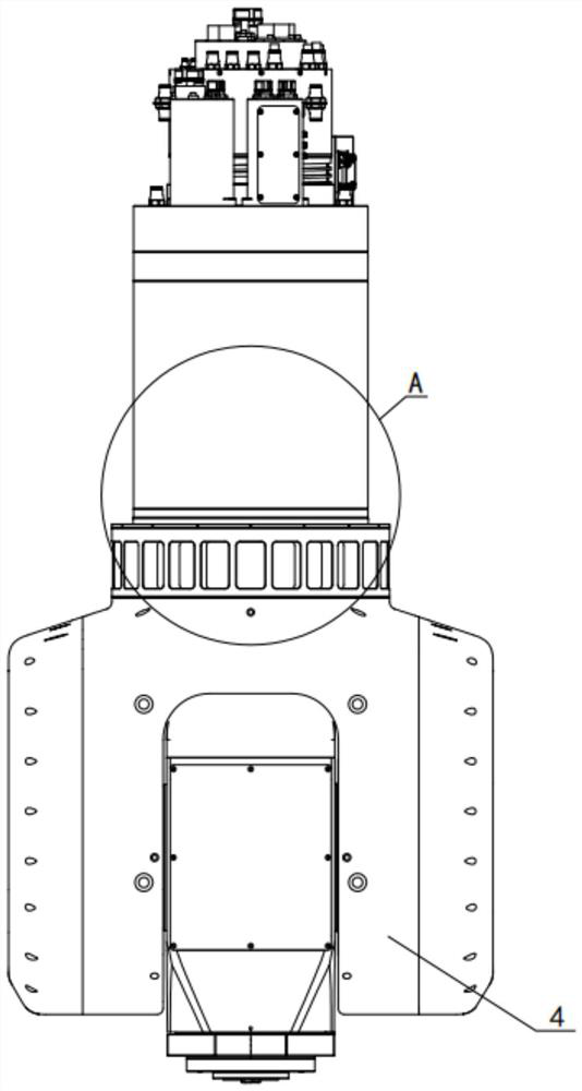
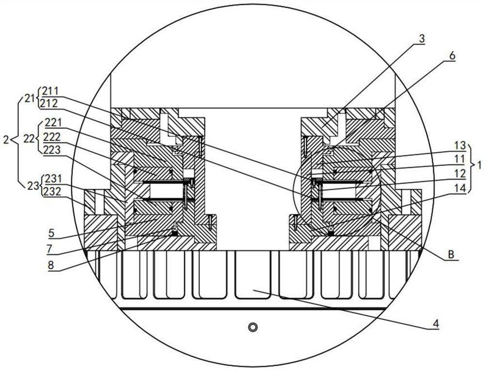
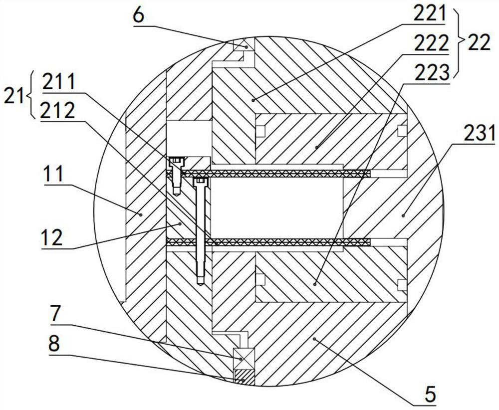
[0024] refer to Figure 1-3 As shown, the present invention discloses a double composite braking device for swinging head, comprising: a rotating mechanism 1, a braking mechanism 2, a motor rotor 3 and a swinging head main body 4; one end of the rotating mechanism 1 is fixedly connected to the bottom of the motor rotor 3 end, and the other end is fixedly connected to the input end of the swing head main body 4; the brake mechanism 2 includes a brake device 21, a drive device 22 and a brake auxiliary assembly 23; the brake device 21 includes a first composite brake disc 211 and The second composite brake disc 212; the first composite brake disc 211 and the second composite brake disc 212 are fixedly connected to the outside of the rotating mechanism 1 at intervals; the output ends of the driving device 22 are respectively located above the first composite brake disc 211 and below the second composite brake disc 212; the inner side of the brake auxiliary assembly 23 is fixedly c...


PUM


Abstract

The invention discloses a head-swinging dual-compound braking device. The head-swinging dual-compound braking device comprises a rotating mechanism, a brake mechanism, a motor rotor and a swing head main body, and is characterized in that the brake mechanism comprises a brake device, a driving device and a brake auxiliary assembly; the brake device comprises a first composite brake disc and a second composite brake disc; the driving device comprises an oil cylinder, a first piston cylinder arranged above the first composite brake disc and a second piston cylinder arranged below the second composite brake disc; the brake auxiliary assembly comprises a spacer bush; and an outer side flange part of the spacer bush is located between the first composite brake disc and the second composite brake disc. According to the head-swinging dual-compound braking device,The piston cylinders are driven by the oil cylinder to extrude the two composite brake discs; air in a cavity between the two composite brake discs is extruded; counter-acting force extrudes the inner sides of the composite brake discs; the composite brake discs are subjected to hydraulic and air pressure effects at the same time; stress on the composite brake discs can be more uniform; in addition, loss in the pressure transmission process can be effectively avoided; braking is more stable; and the braking effect is higher.

Description

technical field [0001] The invention relates to the technical field of oscillating head braking, and more specifically relates to a double compound braking device for oscillating head. Background technique [0002] At present, most of the swing head braking devices in the prior art are single-direction braking, the braking effect is poor, and the force is uneven, the stability is not high, and the braking energy supply mode is mostly single-mode energy supply, which cannot Meet the energy supply requirements under different working conditions. At the same time, the existing braking mechanism mainly uses pneumatic energy supply, which is supplied by compressed air. Due to the compressibility of gas, it is difficult to ensure air tightness, resulting in poor transmission accuracy and low supply capacity, and the pneumatic structure The large volume is not conducive to the flexible rotation of the swing head. [0003] Therefore, how to provide an oscillating head double compo...

Claims


Application Information

Patent Timeline
Patent Type & Authority Applications(China)
IPC IPC(8): F16D55/228F16D65/18F16D121/04
CPCF16D55/228F16D65/18F16D2121/04
Inventor 周康范家成王刚相朝芳李兆龙戴野
Owner 宁波天控五轴数控技术有限公司
Learn More