A display method of led spherical screen

A spherical screen and display method technology, applied in static indicators, identification devices, instruments, etc., to achieve comfortable display effects, rigorous and reasonable design, and high pixel utilization.

Active Publication Date: 2021-11-05
CHENGDU CHENGDIAN GUANGXIN TECH
View PDF6 Cites 0 Cited by
  • Summary
  • Abstract
  • Description
  • Claims
  • Application Information

AI Technical Summary

Problems solved by technology

There is no complete set of design methods for LED spherical screens in the prior art

Method used


Image

  • A display method of led spherical screen
  • A display method of led spherical screen
  • A display method of led spherical screen

Examples


Embodiment 1

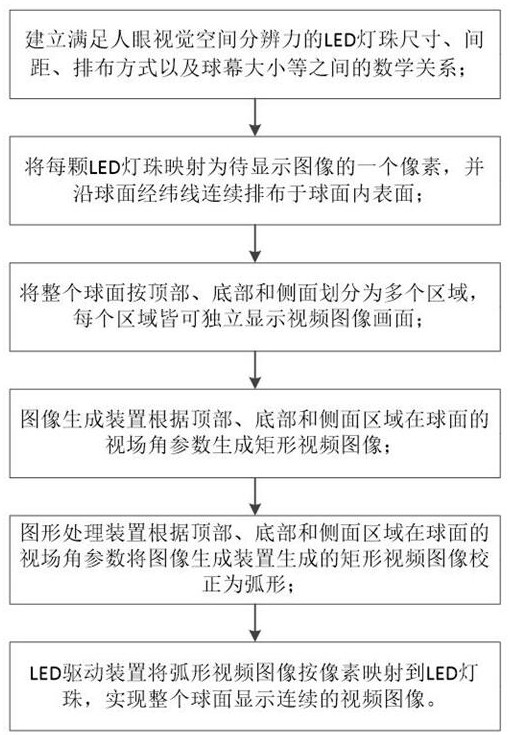
[0059] As a preferred embodiment of the present invention, the present invention adopts LED display technology to replace the original projector display technology, and is composed of three modules: image generation device, graphics processing device and LED display screen. Usually, the size of the LED lamp beads 501 and the spacing of the LED lamp beads 501 of an LED display are usually designed based on experience, lacking more rigorous theoretical support, especially for special-shaped screens such as spherical LED displays, it is necessary to consider more factors. The present invention is based on the theory of human visual spatial resolution, comprehensively considers many factors such as the size of the LED lamp beads 501, the distance between the LED lamp beads 501, the arrangement of the LED lamp beads 501, and the size of the display spherical surface, and establishes a mathematical relationship, so that the design of the LED display screen has theoretical support; t...

Embodiment 2

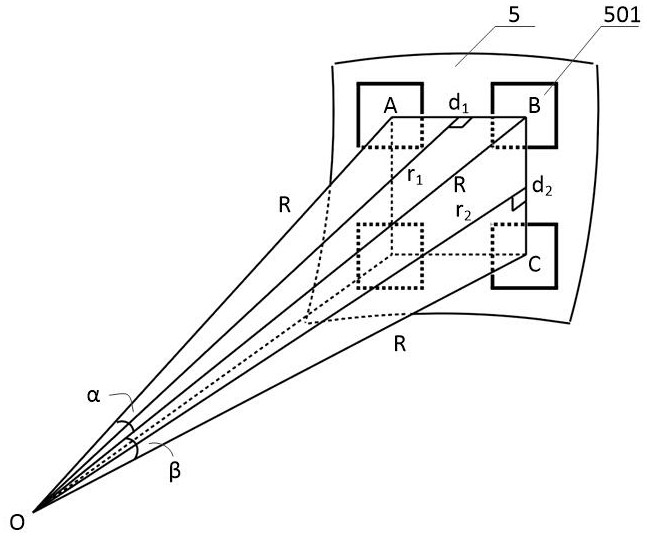
[0069] On the basis of embodiment 1, as the best implementation mode of the present invention, the mathematical relationship in step 1 is as follows figure 2 Shown:

[0070] Definitions A, B, and C respectively represent the LED lamp beads 501 arranged on the LED display spherical surface 5, and the size of each LED lamp bead 501 is d×d, d 1 Indicates the center chord length of two adjacent LED lamp beads 501A and B along the direction of spherical latitude, d2 Indicates the center chord length of two adjacent LED lamp beads 501B and C along the meridian direction of the sphere, O is the center of the sphere, R is the radius of the sphere, which is also equal to the distance from the center of the sphere to each LED 501 on the sphere, r 1 and r 2 are the distance from the center of the sphere to the line segment AB and the distance from the center of the sphere to the line segment BC, respectively, where α=∠AOB and β=∠BOC are defined as the spatial resolution angle.

[0071...

example 1

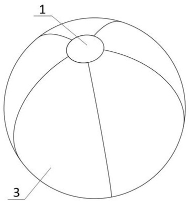
[0095] Such as Figure 1 to Figure 7 As shown, the marks in the figure: 1, top area, 101, north pole, 2, bottom area, 201, south pole, 3, side area, 31, first sub-area, 32, second sub-area, 33, third Sub-area, 34, fourth sub-area, 3i, i-th sub-area, 40, equator line, 5, LED display spherical surface, 501, LED lamp bead.

[0096] 1) The radius of the ball screen is 3500mm.

[0097] 2) According to the mathematical formula, it is known that the radius of the spherical screen is R=3500mm, and the LED lamp beads are evenly spaced along the longitude and latitude lines, that is , while taking , can be calculated by formula (3) , choose The size of the LED lamp beads can be.

[0098] 3) Divide the top, bottom and side areas, where the side is divided into 6 areas according to the same horizontal field of view, then the horizontal field of view of each area .

[0099] 4) The viewing angles of the top and bottom areas are designed to be 40°, and all vertical viewing angles...


PUM


Abstract

The invention discloses a LED spherical screen display method, and relates to the technical field of LED spherical screen display. Based on the theory of human visual spatial resolution, comprehensive consideration is given to the size of LED lamp beads, the distance between LED lamp beads, the arrangement of LED lamp beads and the display method. There are many factors such as the size of the spherical surface, and a mathematical relationship is established based on this. Each LED lamp bead is defined as a pixel of the image to be displayed, and the spherical surface is formed by continuously arranging the LED lamp beads along the longitude and latitude of the spherical surface, so that it has a spherical display. Video image function, and then by dividing the entire spherical surface into multiple areas according to the top, bottom and side, and according to the field of view parameters of each area, the video image is generated by the image generation device, the image is corrected by the graphics processing device, and the image is driven by the LED drive device, etc. The operation completes the function of displaying continuous video images on the entire spherical surface. The method provides a theoretical basis for the design of the LED spherical screen, and enables human eyes to obtain a more comfortable display effect.

Description

technical field [0001] The invention relates to the technical field of screen display methods, in particular to a LED spherical screen display method. Background technique [0002] The LED visual dome display system is mainly composed of LED display system, video processing system, video transmission system, mechanical structure components and distributed power supply, and is a visual dome with display function. Among them, the LED display body is mainly spliced ​​by LED display modules, and the mechanical structure components include the LED light board carrier based on the aluminum die-casting structure design, the glass fiber reinforced plastic skeleton and the shell decoration board based on the composite material design; the spherical screen video processing system and The video transmission system is also an important part of it. The system is composed of graphics correction equipment, video sending equipment, video receiving card and other components. The graphics cor...

Claims


Application Information

Patent Timeline
Patent Type & Authority Patents(China)
IPC IPC(8): G09F9/33G09G3/32
CPCG09F9/33G09G3/32
Inventor 解军王继岷贺卫东曾一雄王万勤
Owner CHENGDU CHENGDIAN GUANGXIN TECH
Why Eureka
Try Eureka