Broadband dual-frequency dual-circularly polarized reflectarray antenna with independently controllable beams

A reflectarray antenna and dual circular polarization technology, applied in antenna, slot antenna, antenna coupling and other directions, can solve the problems of low frequency, complex structure, and multiple functional layers of dual frequency, and achieve wide bandwidth, low profile, and easy integrated effect

Active Publication Date: 2022-03-29
SOUTHEAST UNIV +1
View PDF9 Cites 0 Cited by
  • Summary
  • Abstract
  • Description
  • Claims
  • Application Information

AI Technical Summary

Problems solved by technology

The existing dual-frequency dual circularly polarized reflectarray antennas are divided into two categories, one is based on multi-functional layers, the upper layer is a dual-frequency line circular polarization converter, and the lower layer is a dual-frequency linearly polarized reflectarray antenna. The disadvantage is that there are many functional layers, complex structure, high profile, and narrow bandwidth; the other type is based on circuit implementation, and an orthogonal coupler is loaded under the dual-frequency radiator with a common aperture to realize dual-frequency dual circularly polarized reflective arrays. Antenna, its disadvantage is that the bandwidth is narrow and the frequency of dual frequency is relatively small

Method used


Image

  • Broadband dual-frequency dual-circularly polarized reflectarray antenna with independently controllable beams
  • Broadband dual-frequency dual-circularly polarized reflectarray antenna with independently controllable beams
  • Broadband dual-frequency dual-circularly polarized reflectarray antenna with independently controllable beams

Examples


Embodiment Construction

[0044] Below in conjunction with accompanying drawing, the present invention will be further described

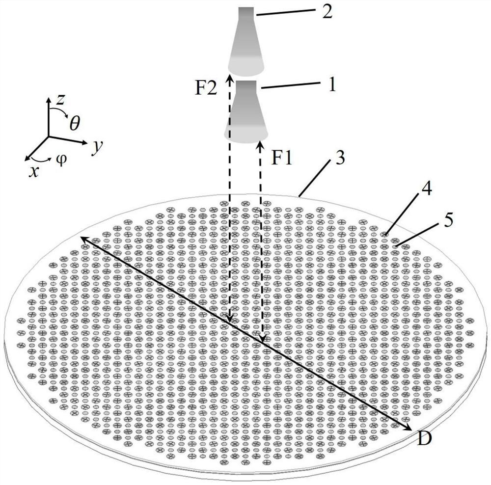
[0045] Such as figure 1 As shown, the present invention proposes a broadband dual-frequency dual circularly polarized reflectarray antenna with independently controllable beams. The reflectarray antenna includes a K-band broadband circularly polarized feed 1, a Ka-band broadband circularly polarized feed 2 and a Flat reflective array3. Both the K-band broadband circularly polarized feed 1 and the Ka-band broadband circularly polarized feed 2 are placed near the focal plane of the planar reflector array 3 . The diameter of the planar reflector array 3 is D, which is set to 180mm here. The vertical distance between the K-band broadband circularly polarized feed source 1 and the planar reflector array 3 is F1, and the value of F1 / D is between 1 and 1.5. Here, it is set is 1.2; the vertical distance between the Ka-band broadband circularly polarized feed 2 and the planar refl...


PUM


Abstract

The invention relates to the field of electronic devices for wireless communication systems, and discloses a broadband dual-frequency dual-circular polarization reflection array antenna with independently controllable beams, including a dual-band broadband circular polarization feed source and a planar reflection array, and a dual-band broadband circular polarization antenna. The feed source is placed near the focal plane of the planar reflector array. The planar reflector array includes low-frequency and high-frequency dual circularly polarized phase-shift units arranged alternately in a common aperture period. Each dual-circularly polarized phase-shift unit includes a circular patch Layer, metal formation with I-shaped gap etched, two microstrip line layers with different lengths and metal backplane layer, etc. The present invention combines the dynamic phase and the rotation phase, and realizes the simultaneous independent regulation of the left-handed phase and the right-handed phase in both the K-band and the Ka-band, and adopts the forms of cross-shaped gap processing and microstrip line gap coupling patches to ensure The ultimate dual-frequency broadband characteristics of the reflectarray antenna have the advantages of low profile, easy processing, easy integration and low cost, and have important application prospects in satellite communications and other fields.

Description

technical field [0001] The invention belongs to the field of electronic devices for wireless communication systems, and in particular relates to a broadband dual-frequency dual-circular polarization reflection array antenna with independently controllable beams. Background technique [0002] At present, the normal work of space probes usually depends on satellite communication, and the commonly used satellite communication frequency bands include C, K and Ka bands. Both K-band and Ka-band refer to a specific radio frequency range. K-band refers to radio waves with a frequency in the range of 18-26.5GHz, and Ka-band refers to radio waves with a frequency in the range of 26.5-40GHz. In order to achieve long-distance and stable communication requirements, it is usually necessary to use high-gain circularly polarized antennas at both the transmitting end and the receiving end of the communication, such as phased array antennas, reflector antennas, etc. [0003] The phased array...

Claims


Application Information

Patent Timeline
Patent Type & Authority Patents(China)
IPC IPC(8): H01Q15/14H01Q3/26H01Q1/52H01Q13/10H01Q1/48
CPCH01Q15/14H01Q3/26H01Q1/52H01Q13/106H01Q1/48
Inventor 蒋之浩童宣锋洪伟
Owner SOUTHEAST UNIV
Why Eureka
Try Eureka