Supercharge Your Innovation With Domain-Expert AI Agents!

Rough turning machining equipment and machining process for primary projectile body part

A processing equipment and rough turning technology, which is applied in the field of projectile parts processing, can solve the problems of small range of motion, prolonged processing time, and reduced production efficiency, and achieves the effect of wide range of motion, not easy to shift, and good flexibility.

Pending Publication Date: 2021-07-09
ANHUI DONGFENG MACHINERY & ELECTRONICS TECHNCO
View PDF8 Cites 0 Cited by
  • Summary
  • Abstract
  • Description
  • Claims
  • Application Information

AI Technical Summary

Problems solved by technology

[0002] At present, with the rapid development of the economy, the demand for CNC machinery is increasing, and the processing industries such as machinery, woodworking, and stone have higher and higher requirements for processing accuracy and higher processing efficiency. The demand is also increasing. As one of the rough turning equipment, the CNC machine tool has become the necessary equipment for the production of enterprises. The range is not large, which is not convenient for rough turning processing. During the processing of projectile parts, there is a situation that the material is easily shaken due to poor fixing effect, resulting in an empty knife, which prolongs the processing time and reduces the production efficiency.

Method used


Image

  • Rough turning machining equipment and machining process for primary projectile body part
  • Rough turning machining equipment and machining process for primary projectile body part
  • Rough turning machining equipment and machining process for primary projectile body part

Examples


Embodiment Construction

[0023] The following will clearly and completely describe the technical solutions in the embodiments of the present invention with reference to the accompanying drawings in the embodiments of the present invention. Obviously, the described embodiments are only some, not all, embodiments of the present invention. Based on the embodiments of the present invention, all other embodiments obtained by persons of ordinary skill in the art without creative efforts fall within the protection scope of the present invention.

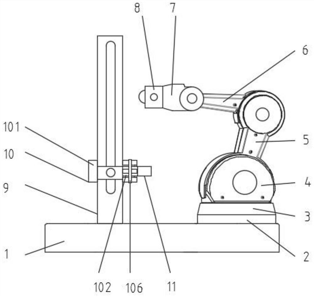
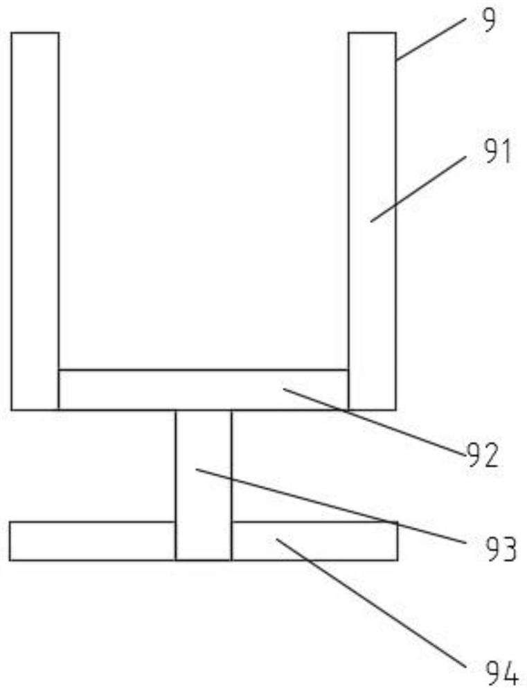
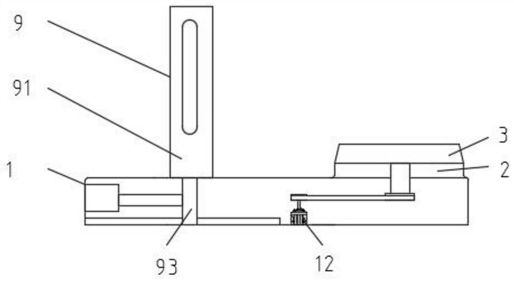
[0024] see Figure 1-4 As shown, a rough turning processing equipment for first-class projectile body parts, including a base plate 1, a fixed column 2, a rotating block 1, a fixed block 4, a rotating block 2 5, a rotating block 3 6, a rotating block 4 7, and an installation block 8 , moving mechanism 9, fixing mechanism 10, projectile body workpiece 11 and power motor 12, the upper end of described base plate 1 is provided with fixed column 2, rotating block one 3...


PUM


Abstract

The invention discloses rough turning machining equipment for a primary projectile body part. The rough turning machining equipment for the primary projectile body part comprises a bottom plate, a fixing column, a rotating block I, a fixing block, a rotating block II, a rotating block III, a rotating block IV, an installation block, a moving mechanism, a fixing mechanism, a projectile body workpiece and a power motor, wherein the fixing column, the rotating block I, the fixing block and the moving mechanism are arranged at the upper end of the bottom plate; and the fixing column, the rotating block I and the fixing block are all located at one side of the moving mechanism, the rotating block I is located between the fixing column and the fixing block, the fixing column is located below the fixing block, and the fixing mechanism is installed on the moving mechanism. According to the invention, the arranged locating rods, limiting rods, clamping hoops and fixing pieces are used in cooperation, the fixing pieces are firmly fixed among the plurality of limiting rods, detachment and installation are facilitated, during rough turning machining, the fixing pieces are not machined, only machined pieces are machined, and the fixing pieces are used for guaranteeing that the positions of the machined pieces cannot deviate during machining, so that the empty turning probability of a turning tool is reduced.

Description

technical field [0001] The invention relates to the technical field of elastic body parts processing, in particular to a first-level rough turning processing equipment for elastic body parts and a processing technology thereof. Background technique [0002] At present, with the rapid development of the economy, the demand for CNC machinery is increasing, and the processing industries such as machinery, woodworking, and stone have higher and higher requirements for processing accuracy and higher processing efficiency. The demand is also increasing. As one of the rough turning equipment, the CNC machine tool has become the necessary equipment for the production of enterprises. The range is not large, and it is not convenient for rough turning. During the processing of projectile parts, there is a situation that the material is easily shaken due to poor fixing effect, resulting in an empty tool, which prolongs the processing time and reduces the production efficiency. Content...

Claims


Application Information

Patent Timeline
Patent Type & Authority Applications(China)
IPC IPC(8): B23B1/00B23B5/00B23Q3/04B23Q3/06B23Q5/02B23Q15/24
CPCB23B5/00B23Q5/02B23Q3/04B23Q3/06B23Q15/24B23B1/00
Inventor 李宏炼唐敏汪文乐吴松松王轩
Owner ANHUI DONGFENG MACHINERY & ELECTRONICS TECHNCO
Features
  • R&D
  • Intellectual Property
  • Life Sciences
  • Materials
  • Tech Scout
  • Unparalleled Data Quality
  • Higher Quality Content
  • 60% Fewer Hallucinations
Learn More