Series reconfigurable variable-stiffness robot joint structure based on permanent magnet spring

A technology of robot joints and permanent magnet springs, applied in manipulators, program-controlled manipulators, manufacturing tools, etc., can solve problems such as insufficient load capacity of variable stiffness joints, complex structure of variable stiffness devices, and increased joint mass and inertia. Human-computer interaction safety, simple structure, and the effect of reducing joint energy consumption

Active Publication Date: 2021-07-09
SHENYANG LIGONG UNIV
View PDF6 Cites 2 Cited by
  • Summary
  • Abstract
  • Description
  • Claims
  • Application Information

AI Technical Summary

Problems solved by technology

1) There is a contradiction between the stiffness adjustment range and the stiffness adjustment accuracy of variable stiffness joints. For example, the spring pre-stretching length, the position of the lever loading point, and the effective length of the reed are all limited to a limited range by the joint size constraints. Therefore, the stiffness adjustment The larger the range, the lower the adjustment resolution
2) The bearing capacity of large variable stiffness joints is insufficient in the low stiffness state
3) The range of stiffness adjustment cannot be changed as the internal structure of the variable stiffness device is determined, and the scope of application is small
4) The variable stiffness devices of most joints have complex structures, which increase the mass and inertia of the joints

Method used


Image

  • Series reconfigurable variable-stiffness robot joint structure based on permanent magnet spring
  • Series reconfigurable variable-stiffness robot joint structure based on permanent magnet spring
  • Series reconfigurable variable-stiffness robot joint structure based on permanent magnet spring

Examples


Embodiment Construction

[0022] The present invention will be further described in detail below in conjunction with the accompanying drawings and embodiments.

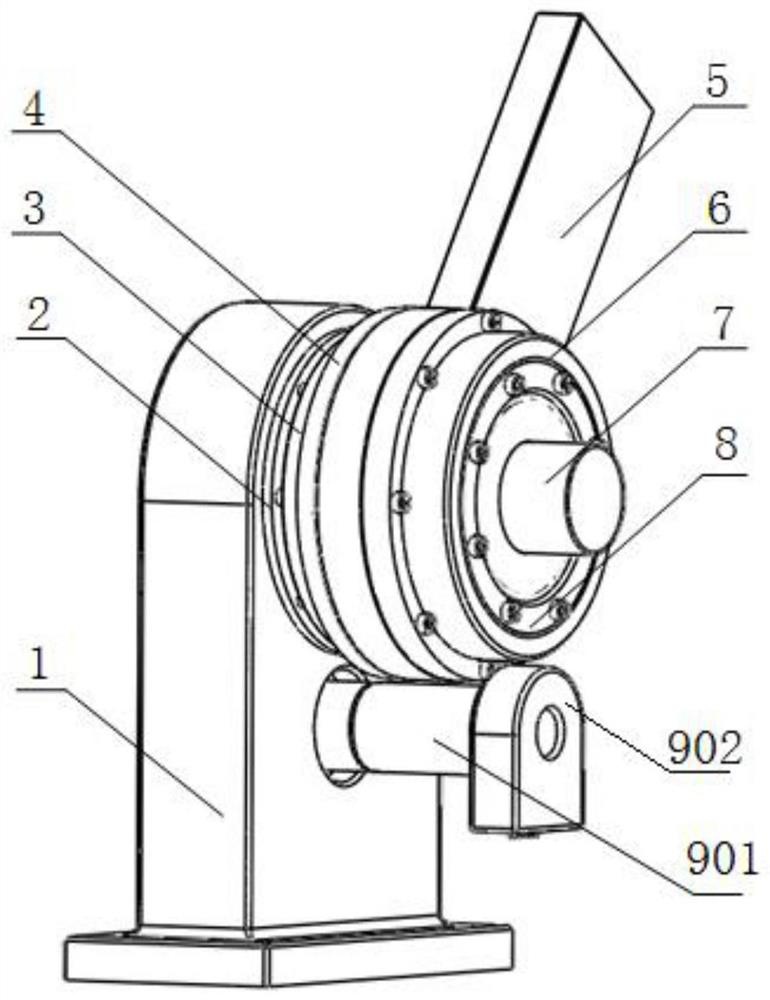
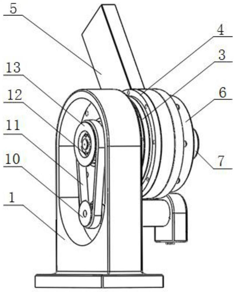
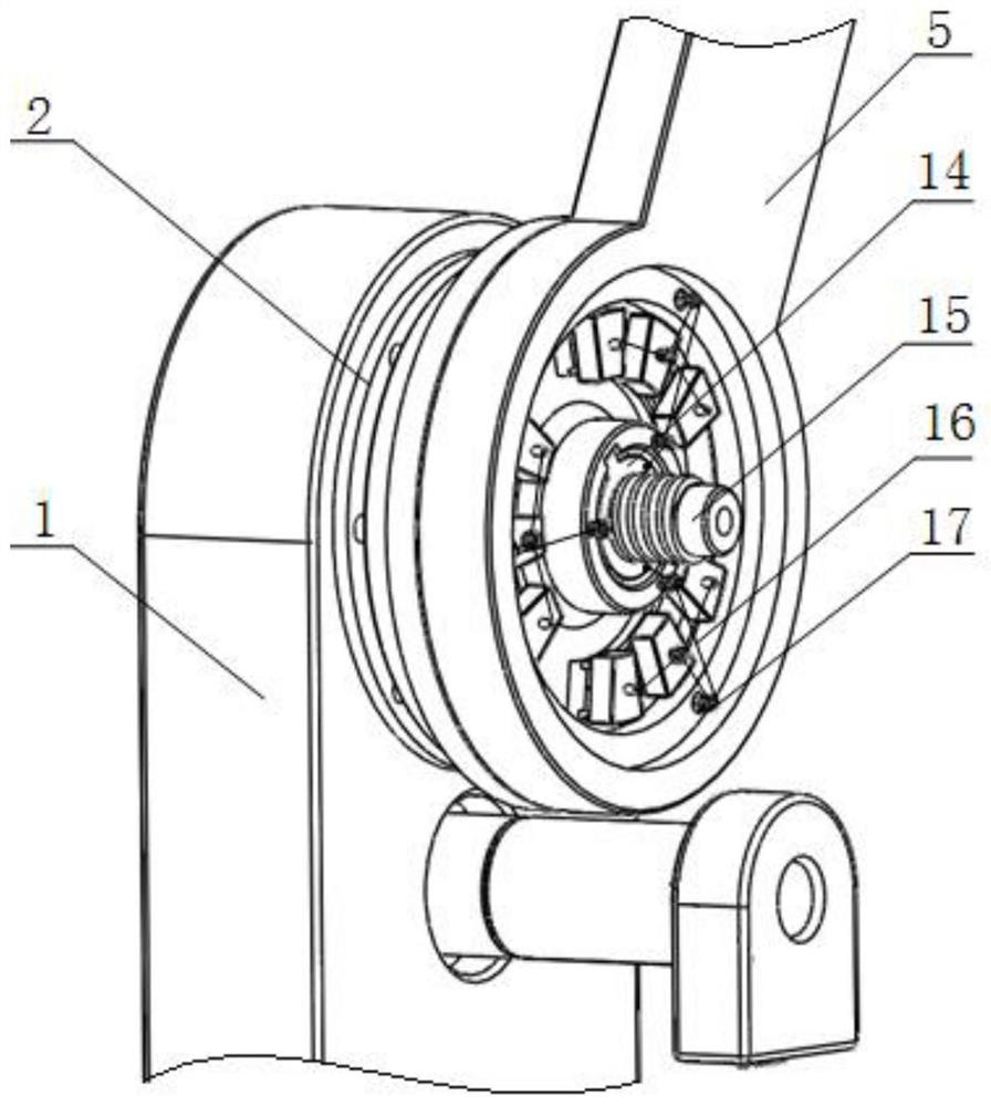
[0023] Such as Figure 1 to Figure 4 As shown, a series reconfigurable variable stiffness robot joint structure based on permanent magnet springs includes a base 1, a rope 16, and a variable stiffness motor 7; one end of the vertical base of the base 1 is processed into a waist-shaped blind hole, The other end is processed with an upper through hole and a lower through hole connected with the waist-shaped blind hole. In the lower through hole, a rotating shaft I is installed through a bearing. One end is fixedly installed on the upper surface of the base 1, and the other end is located in the waist-shaped blind hole, and a small pulley 10 is partially installed; the output disc 3 is a disc with a shaft body 12, and the upper through hole passes through the cross roller. The sub-bearing I2 is rotatably installed with the shaft body 12 of the o...


PUM


Abstract

A series reconfigurable variable-stiffness robot joint structure based on a permanent magnet spring comprises a base, a rope and a variable-stiffness motor. A kidney-shaped blind hole is machined in one end of a vertical base body of the base, an upper through hole and a lower through hole which are communicated with the kidney-shaped blind hole are machined in the other end of the vertical base body, a rotating shaft I is installed in the lower through hole through a bearing, one end of the rotating shaft I is sequentially connected with a speed reducer and a position servo motor, and a small belt wheel is installed on the portion, located in the kidney-shaped blind hole, of the other end of the rotating shaft I. A shaft body of an output disc is rotationally installed in the upper through hole through a crossed roller bearing I, the end face of the crossed roller bearing I is fixedly connected with one end of a disc of the output disc, a large belt wheel is installed on the portion, located in the kidney-shaped blind hole, of the shaft body of the output disc, a synchronous belt is installed between the large belt wheel and the small belt wheel, and the disc of the output disc is sequentially connected with a connecting rod disc and a variable-stiffness device through a crossed roller bearing II. The variable-stiffness device changes the stiffness adjusting range by rapidly adjusting the arrangement mode of the permanent magnet spring and the rope, and the application range is wider.

Description

technical field [0001] The invention belongs to the technical field of a series reconfigurable variable stiffness joint structure of a flexible robot system, and in particular relates to a series reconfigurable variable stiffness robot joint structure based on a permanent magnet spring. Background technique [0002] At present, robots have penetrated into all aspects of people's daily production and life and are showing explosive growth. The demand for the integration of robots and humans in the fields of smart factories, elderly and disabled services, medical care, education and entertainment is gradually increasing. The security issue of human-computer interaction has been paid more and more attention. The use of flexible variable stiffness joint actuators to achieve robot compliance and active adaptability has attracted more and more attention from researchers. [0003] At present, the variable stiffness joint driver mainly adopts the following schemes: ① Impedance contr...

Claims


Application Information

Patent Timeline
Patent Type & Authority Applications(China)
IPC IPC(8): B25J17/00B25J17/02B25J9/12B25J9/10
CPCB25J17/00B25J17/0208B25J9/126B25J9/104
Inventor 孙龙飞都智勇
Owner SHENYANG LIGONG UNIV
Why Eureka
Try Eureka