Stripping device and stripping method

A technology of peeling device and mounting bracket, which is used in transportation and packaging, thin material processing, winding strips, etc., and can solve problems such as the inability to successfully complete the peeling action.

Active Publication Date: 2021-07-09
SHENZHEN CHINA STAR OPTOELECTRONICS TECH CO LTD
View PDF5 Cites 1 Cited by
  • Summary
  • Abstract
  • Description
  • Claims
  • Application Information

AI Technical Summary

Problems solved by technology

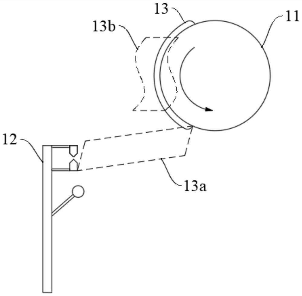
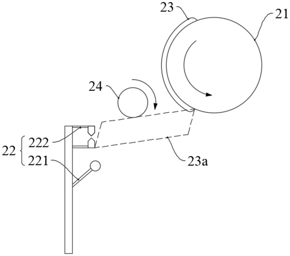
[0005] The embodiment of the present invention provides a peeling device and a peeling method, which are used to solve the problem in the prior art that when the peeling head peels the film on the outside of the adhesive material, the film rebounds and curls due to tension, and reattaches to the roller, which cannot Successful completion of technical issues such as stripping

Method used


Image

  • Stripping device and stripping method
  • Stripping device and stripping method
  • Stripping device and stripping method

Examples


Embodiment Construction

[0033] The following will clearly and completely describe the technical solutions in the embodiments of the present invention with reference to the drawings in the embodiments of the present invention. Apparently, the described embodiments are only some of the embodiments of the present invention, but not all of them. Based on the embodiments of the present invention, all other embodiments obtained by those skilled in the art without creative efforts fall within the protection scope of the present invention.

[0034] In describing the present invention, it should be understood that the terms "center", "longitudinal", "transverse", "length", "width", "thickness", "upper", "lower", "front", " Orientation indicated by rear, left, right, vertical, horizontal, top, bottom, inside, outside, clockwise, counterclockwise, etc. The positional relationship is based on the orientation or positional relationship shown in the drawings, which is only for the convenience of describing the pr...


PUM


Abstract

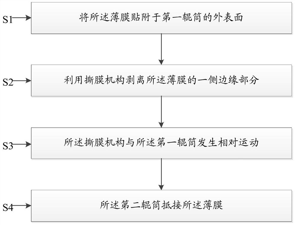
The invention discloses a stripping device and a stripping method. The stripping device is used for stripping films and comprises a first roller, a first film tearing mechanism and a second roller, wherein the films are attached on the outer surface of the first roller; the film tearing mechanism is arranged below the first roller; and the second roller is arranged between the first roller and the film tearing mechanism and is used for abutting against the films during stripping. Compared with the existing stripping device and stripping method, the stripping device has the advantages that the second roller is additionally arranged in the stripping device and is arranged between the first roller and the film tearing mechanism; when the films rebound and curl due to tension, the second roller can block the rebounding tracks of the films, so that the films are attached on the second roller and are prevented from being attached on the first roller; and the stripping action is smoothly completed.

Description

technical field [0001] The invention relates to the field of display technology, in particular to a stripping device and a stripping method. Background technique [0002] The lamination (Lami) equipment is mainly to attach the barrier layer (Barrier Film) or Metal foil (Metal Foil), in order to protect the OLED panel, prevent external water and oxygen from intruding, and play a role in preventing debris (Particle) and external force damage. [0003] The current specific steps of bonding include: firstly, the film is indirectly pasted on the roller through the adhesive material, secondly, the film outside the adhesive material is peeled off through the peeling head, and finally the film is transferred to the glass substrate through the roller. However, there is a technical problem in the peeling step: when the peeling head peels off the film on the outside of the adhesive material, the film rebounds and curls due to tension, and reattaches to the roller, so the peeling actio...

Claims


Application Information

Patent Timeline
Patent Type & Authority Applications(China)
IPC IPC(8): B65H41/00B65H27/00H05F3/06
CPCB65H41/00B65H27/00H05F3/06
Inventor 张敏
Owner SHENZHEN CHINA STAR OPTOELECTRONICS TECH CO LTD
Why Eureka
Try Eureka