
Steering device special for wind power tower drum

A steering device, wind power tower technology, applied in the directions of transportation and packaging, load hanging components, etc., can solve the problems of damage to the outer wall paint of the tower, easy rust of the tower, etc., to avoid paint damage, convenient production, and avoid damage. Effect

Pending Publication Date: 2021-07-09
HUNAN LEED METAL STRUCTURE
View PDF0 Cites 1 Cited by
  • Summary
  • Abstract
  • Description
  • Claims
  • Application Information

AI Technical Summary

Problems solved by technology

[0004] Based on the existing special steering device for wind power towers, the existing method often seriously damages the paint on the outer wall of the tower when the steering device is used as the fulcrum, which in turn leads to the technical problem that the tower is easy to rust during normal use. The present invention A special steering device for wind power towers is proposed

Method used


Image

  • Steering device special for wind power tower drum
  • Steering device special for wind power tower drum
  • Steering device special for wind power tower drum

Examples


Embodiment 1

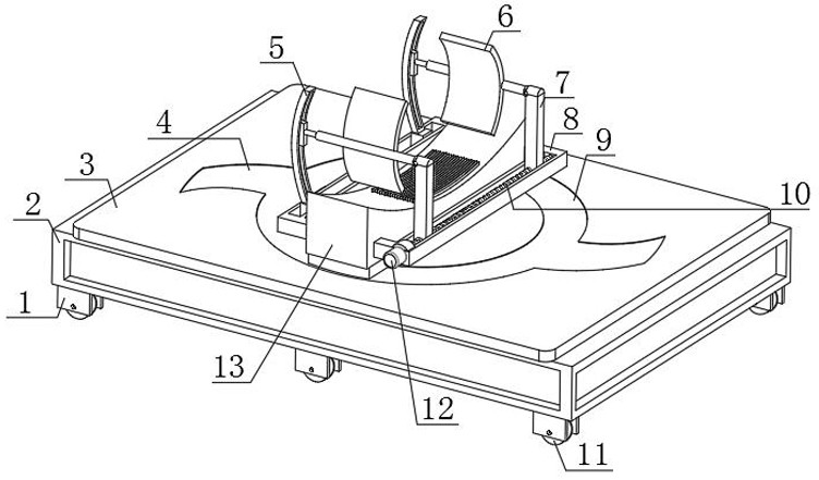
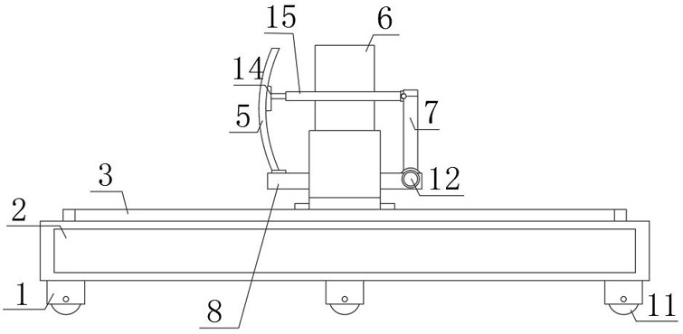
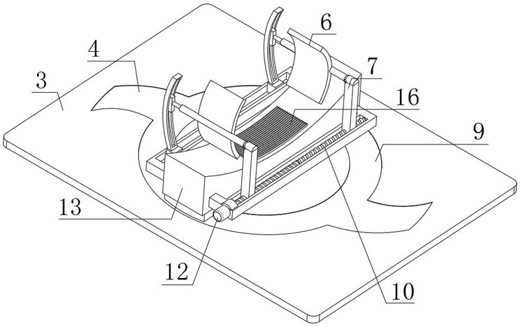
[0029] refer to Figure 1-5 , a special steering device for wind power towers, comprising a main body frame 2, a steering platform 3 is fixedly connected to the top outer wall of the main body frame 2, a mounting pad 17 is fixedly connected to the central position of the top outer wall of the steering platform 3, and the top outer wall of the mounting pad 17 A rotating shaft is provided at the central position, and a lower anti-wear copper sheet 18 and an upper anti-wear copper sheet 19 are sleeved on the outer wall of the rotating shaft. A sleeve 20 is sleeved on the outer wall of the rotating shaft, and plugs are provided on the outer walls of both sides of the sleeve 20. 23. The top of the casing 20 is fixedly connected to the saddle support 13, the lower anti-wear copper sheet 18 is fixedly connected to the mounting pad 17, and the upper anti-wear copper sheet 19 is fixedly connected to the top outer wall of the saddle support 13, and the saddle support Both sides outer wa...

Embodiment 2

[0040] refer to Figure 6 , a special steering device for wind power towers, comprising a main body frame 2, a steering platform 3 is fixedly connected to the top outer wall of the main body frame 2, a mounting pad 17 is fixedly connected to the central position of the top outer wall of the steering platform 3, and the top outer wall of the mounting pad 17 A rotating shaft is provided at the central position, and a lower anti-wear copper sheet 18 and an upper anti-wear copper sheet 19 are sleeved on the outer wall of the rotating shaft. A sleeve 20 is sleeved on the outer wall of the rotating shaft, and plugs are provided on the outer walls of both sides of the sleeve 20. 23. The top of the casing 20 is fixedly connected to the saddle support 13, the lower anti-wear copper sheet 18 is fixedly connected to the mounting pad 17, and the upper anti-wear copper sheet 19 is fixedly connected to the top outer wall of the saddle support 13, and the saddle support Both sides outer wall...


PUM


Abstract

The invention discloses a steering device special for a wind power tower drum, and aims at solving the problems that paint on the outer wall of the tower drum is seriously damaged and the tower drum is easy to rust during normal use during rotation by taking a steering device as a fulcrum in an existing manner. According to the scheme, the steering device comprises a main body frame, a steering platform is fixedly connected to the outer wall of the top of the main body frame, a mounting pad is fixedly connected to the center of the outer wall of the top of the steering platform, a rotating shaft is arranged at the center of the outer wall of the top of the mounting pad, the outer wall of the rotating shaft is sleeved with a lower anti-abrasion copper sheet and an upper anti-abrasion copper sheet, and the outer wall of the rotating shaft is sleeved with a sleeve. Due to the fact that connecting rods are connected to sliding supporting rods through hinges, clamping frames can rotate adaptively during turning lifting of a tower crane while being attached to the outer wall of the tower drum to be fixed, the stability of the tower drum is effectively guaranteed, and the anti-corrosion paint on the outer wall of the tower drum is prevented from being damaged.

Description

technical field [0001] The invention relates to the technical field of steering devices, in particular to a special steering device for a wind power tower. Background technique [0002] At present, the wind power tower is a key supporting part of the wind power generation unit. As the technology becomes more and more mature, the installed capacity of the unit is increasing. The onshore unit is 2.5MW, 3.0MW, 3.2MW, 4.8MW, and the offshore unit is 5.0MW. , 6.45MW, 8.3MW, etc., with the increase of installed capacity, the diameter of the tower is getting larger and larger, and the weight of a single-section tower is also increasing, and the requirements for the lifting capacity of the manufacturing plant are also increasing. come higher. With the requirements of national policies on carbon emissions, wind power, as a clean energy source, has invested more and more, and more and more projects have been launched. There are also more and more towers with large diameters and large...

Claims


Application Information

Patent Timeline
Patent Type & Authority Applications(China)
IPC IPC(8): B66C13/08
CPCB66C13/08
Inventor 胡朗林畅徐梅周凯
Owner HUNAN LEED METAL STRUCTURE
Learn More