Combustion chamber laminate and combustion chamber

A combustion chamber and outer layer technology, applied in the field of combustion chamber laminates and combustion chambers, can solve the problems of limited improvement potential of cooling efficiency, influence on combustion chamber performance, large pressure loss, etc., and achieve the effect of improving cooling performance

Pending Publication Date: 2021-07-09
CHINA UNITED GAS TURBINE TECH CO LTD
View PDF6 Cites 3 Cited by
  • Summary
  • Abstract
  • Description
  • Claims
  • Application Information

AI Technical Summary

Problems solved by technology

For the hot components of the combustor whose main cooling method is impingement cooling, further improvement of the cooling performance often means reducing the hole diameter and the distance between the impact holes, etc., resulting in a large pressure loss, affecting the performance of the combustor, and affecting the cooling efficiency. limited potential for improvement

Method used


Image

  • Combustion chamber laminate and combustion chamber
  • Combustion chamber laminate and combustion chamber
  • Combustion chamber laminate and combustion chamber

Examples


Embodiment 1

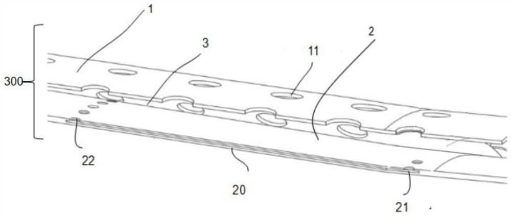
[0040] Such as figure 1 As shown, the combustion chamber laminate 300 includes an outer wall 1 and an inner wall 2 , and the outer wall 1 and the inner wall 2 together form a sandwich channel 3 . A plurality of impingement cooling holes 11 are provided on the outer wall 1 , and in one embodiment of this application, the plurality of impingement cooling holes 11 are arranged side by side along the circumference of the outer wall 1 , and serve as inlets for air entering the interlayer passage 3 .

[0041] The inner wall 2 of the flame tube or the transition section is a laminate structure, and there is a laminate channel 20 inside the laminate structure, and the air flow can circulate in the laminate channel 20, and the inner wall 2 is provided with a laminate inflow hole 21, a laminate channel 20 and laminate outflow holes 22, in one embodiment of the application, the inner wall 2 is provided with a plurality of laminate inflow holes 21 and a plurality of laminate outflow holes...

Embodiment 2

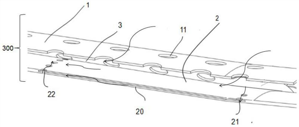
[0045] Such as image 3 As shown, the combustion chamber laminate 300 includes an outer wall 1 and an inner wall 2 , and the outer wall 1 and the inner wall 2 together form a sandwich channel 3 . Multiple impingement cooling holes 11 are provided on the outer wall 1 , and in one embodiment of this application, the multiple impingement cooling holes 11 are arranged side by side along the circumference of the outer wall 1 , and serve as inlets for cold air entering the interlayer passage 3 .

[0046] The inner wall 2 of the flame tube or the transition section is a laminate structure, and there is a laminate channel 20 inside the laminate structure, and the air flow can circulate in the laminate channel 20, and the inner wall 2 is provided with a laminate inflow hole 21, a laminate channel 20 and laminate outflow holes 22, in one embodiment of the application, the inner wall 2 is provided with a plurality of laminate inflow holes 21 and a plurality of laminate outflow holes 22, ...

Embodiment 3

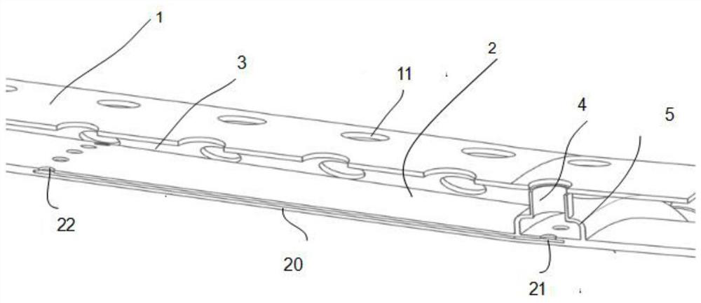
[0052] The combustion chamber laminate 300 includes an outer wall 1 and an inner wall 2 , and the outer wall 1 and the inner wall 2 jointly form a sandwich channel 3 . A plurality of impingement cooling holes 11 are provided on the outer wall 1 , and in one embodiment of the application, the plurality of impingement cooling holes 11 are arranged side by side along the circumference of the outer wall 1 , and serve as inlets for air entering the interlayer passage 3 .

[0053] The inner wall 2 of the flame tube or the transition section is a laminate structure, and there is a laminate channel 20 inside the laminate structure, and the air flow can circulate in the laminate channel 20, and the inner wall 2 is provided with a laminate inflow hole 21, a laminate channel 20 and laminate outflow holes 22, in one embodiment of the application, the inner wall 2 is provided with a plurality of laminate inflow holes 21 and a plurality of laminate outflow holes 22, a plurality of laminate i...


PUM


Abstract

The invention discloses a combustion chamber laminate which comprises an outer layer wall and an inner layer wall, and the outer layer wall and the inner layer wall jointly form an interlayer channel. A plurality of impact cooling holes are formed in the outer layer wall. The inner layer wall is provided with a laminate inflow hole, a laminate channel and a laminate outflow hole. First airflow flows into the interlayer channel from the impact cooling holes of the outer layer wall to form impact cooling on the inner layer wall, and flows in the upstream direction along the interlayer channel. Second airflow flows into the interlayer from the impact cooling holes of the outer layer wall, flows into the laminate channel through the laminate inflow hole, flows in the upstream direction along the laminate channel, flows out from the laminate outflow hole, enters the interlayer channel to be converged with the first airflow and flows to an inlet of a combustion chamber. According to the combustion chamber laminate and the combustion chamber, the cooling performance of a combustion chamber flame tube or a transition section is improved.

Description

technical field [0001] The present application relates to the field of gas turbines, in particular to a combustor layer plate and a combustor. Background technique [0002] A gas turbine mainly includes three major components: a compressor, a combustion chamber, and a turbine. The exhaust gas from the compressor is mixed with fuel in the combustion chamber to participate in combustion, and the generated hot gas is sent to the turbine to perform work. The main function of the combustion chamber transition section is to provide a circular fan-shaped gas channel to guide the hot gas from the head of the combustion chamber to the turbine blades to perform work. Since the inside of the combustor flame tube and the transition section are scoured by high-temperature gas, they need to be cooled by the exhaust gas of the compressor. [0003] Patent CN111380077A discloses that the burner includes a flame tube, a flow liner and a flow guiding device. The flow liner is set on the flame...

Claims


Application Information

Patent Timeline
Patent Type & Authority Applications(China)
IPC IPC(8): F23R3/00F23R3/52
CPCF23R3/002F23R3/52F23R2900/03045
Inventor 杨旭李珊珊段冬霞刘立静
Owner CHINA UNITED GAS TURBINE TECH CO LTD
Why Eureka
Try Eureka