Transformer oil gas content testing device and a transformer oil gas content testing method and device for measuring density through U-shaped oscillation tube

A transformer oil and testing device technology, applied in measuring devices, specific gravity measurement, instruments, etc., can solve the problems of low measurement results, reduced gas phase gas component concentration, undetectable gas, etc., achieve high measurement accuracy, simple operation, avoidance of The effect of gas redissolving

Pending Publication Date: 2021-07-09
ELECTRIC POWER RES INST OF STATE GRID ANHUI ELECTRIC POWER +2
View PDF1 Cites 5 Cited by
  • Summary
  • Abstract
  • Description
  • Claims
  • Application Information

AI Technical Summary

Problems solved by technology

However, the problem with this method of carbon dioxide elution is that CO 2 The flow rate is not easy to control precisely, and the potassium hydroxide solution is 2 The absorption efficiency and the determination of the blank value need to be carefully studied. More importantly, this method is only suitable for the determination of the gas content of new oil. 2 The gas cannot be detected, making the measurement result low
In order to improve the degassing efficiency of oil with low gas content, it is generally used to increase the vacuum volume, that is, to increase the volume of the degassing container. Although the degassing efficiency is improved, the concentration of gas components in the gas phase is reduced, and the corresponding vacuum The differential pressure change of the gauge is reduced, which has higher requirements for the precision of the device

Method used


Image

  • Transformer oil gas content testing device and a transformer oil gas content testing method and device for measuring density through U-shaped oscillation tube
  • Transformer oil gas content testing device and a transformer oil gas content testing method and device for measuring density through U-shaped oscillation tube
  • Transformer oil gas content testing device and a transformer oil gas content testing method and device for measuring density through U-shaped oscillation tube

Examples


Embodiment 1

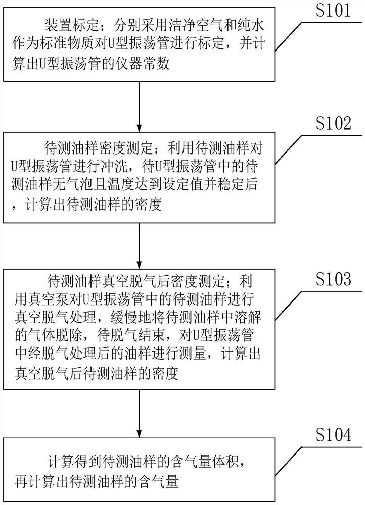
[0053] 1. The connection relationship of the device

[0054] Such as figure 1 As shown, a U-shaped oscillating tube density measuring transformer oil gas content testing device includes: U-shaped oscillating tube 1, magnet 2, electronic excitation oscillator 3, vacuum degassing chamber 4, oil sample buffer chamber 5, vacuum pump 6 , the first temperature sensor 7, the second temperature sensor 8, the third temperature sensor 9, the temperature control insulation layer 10, the first valve 11, the second valve 12, the third valve 13, the fourth valve 14, the fifth valve 15, Sixth valve 16, frequency counter 17.

[0055] The U-shaped oscillating tube 1, magnet 2, electronic excitation oscillator 3, vacuum degassing chamber 4, oil sample buffer chamber 5, first temperature sensor 7, third temperature sensor 9, third valve 13, fourth valve 14. The frequency counter 17 is installed inside the temperature control insulation layer 10; the U-shaped oscillating tube 1 is made of boron...


PUM

PropertyMeasurementUnit
densityaaaaaaaaaa

Abstract

The invention discloses a transformer oil gas content testing device and a transformer oil gas content testing method for measuring density through a U-shaped oscillation tube, belongs to the technical field of electric power system detection, and solves the problem of how to calculate the gas content in oil according to the change of the density of a tested oil sample before and after vacuum degassing so as to improve the testing precision. According to the device, the U-shaped oscillation tube is used for measuring the density of the oil sample, the measuring precision is very high, the requirement for accurate measurement of the density change of the oil sample before and after degassing can be met, and the gas content in the oil is calculated according to the density change of the oil sample before and after vacuum degassing of the measured oil sample for the first time. The method is a test method with a brand new test principle, is simple to operate, facilitates field test and can adapt to measurement of oil samples with different gas contents.

Description

technical field [0001] The invention belongs to the technical field of electric power system detection, and relates to a transformer oil gas content testing device and method for measuring density with a U-shaped oscillating tube. Background technique [0002] The carbon dioxide elution method is to use the supersaturation of carbon dioxide to replace and carry out the dissolved gas in the oil, and then pass through the absorption tube equipped with potassium hydroxide solution at the same time, so that the carbon dioxide is completely absorbed by the lye, so that all the dissolved gas in the oil enters the gas measuring tube , based on which the content of dissolved gas in the oil is determined. However, the problem with this method of carbon dioxide elution is that CO 2 The flow rate is not easy to control precisely, and the potassium hydroxide solution is 2 The absorption efficiency and the determination of the blank value need to be carefully studied. More importantly,...

Claims


Application Information

Patent Timeline
Patent Type & Authority Applications(China)
IPC IPC(8): G01N9/36
CPCG01N9/36
Inventor 刘子恩谢佳刘伟赵跃马凤翔袁小芳祁炯朱峰宋玉梅杭忱
Owner ELECTRIC POWER RES INST OF STATE GRID ANHUI ELECTRIC POWER
Why Eureka
Try Eureka